


© National Instruments Corp. 5 FP-RTD-122 and cFP-RTD-122
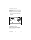
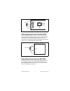
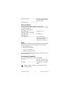
Figure 3. [c]FP-RTD-122 Input Circuitry
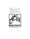
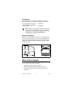
Taking Measurements from Three-Wire RTDs
Three-wire RTDs often have a wire of one color (usually white,
sometimes red) for positive excitation, and two wires of another
color (usually red, sometimes black). Connect the positive
excitation wire to the EX+ terminal of the module, and connect the
other two wires to the SENSE and COM terminals.
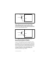
Figure 4. Three-Wire RTD Connections on One Channel
Taking Measurements from Four-Wire RTDs
For the best accuracy, use the NI [c]FP-RTD-124 for input from
four-wire RTDs. Otherwise, leave any one of the RTD wires
unconnected and connect the remaining three as you would for a
three-wire RTD. Refer to Figure 5.
RTD
[c]FP-RTD-122
Pulsed
16-bit
ADC
Input
Circuitry
EX+
SENSE
COM
3-wire RTD
[c]FP-RTD-122
EX+
SENSE
COM