


Chapter 3 Hardware Overview
NI 6115/6120 User Manual 3-2 ni.com
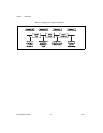
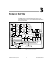
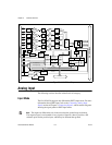
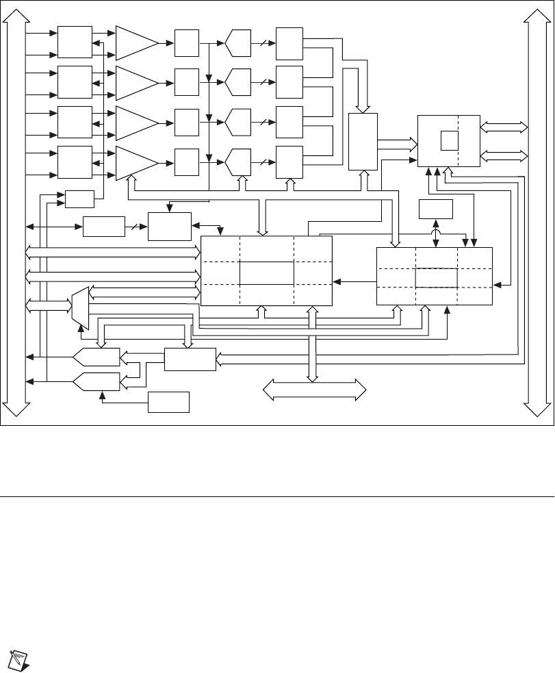
Figure 3-2. NI 6120 Block Diagram
Analog Input
The following sections describe in detail each AI category.
Input Mode
The NI 6115/6120 supports only differential (DIFF) input mode. For more
information about DIFF input, refer to the Connecting Analog Input
Signals section of Chapter 4, Connecting Signals, which contains diagrams
showing the signal paths for DIFF input mode.
Note The inputs are differential only in the sense that the ground loops are broken.
The negative input is not intended to carry signals of interest, rather it provides a DC
reference point for the positive input, which may be different than ground.
Timing
PFI / Trigger
I/O Connector
RTSI Bus
STC Digital I/O (8)
EEPROM
+
CH0
Amplifier
–
Calibration
Mux
AI CH0
Mux
Analog
Trigger
Circuitry
2
Trigger Level
DACs
Trigger
Calibration
DACs
DAC1
DAQ - STC
Analog Input
Timing/Control
Analog Output
Timing/Control
Digital I/O
Trigger
Counter/
Timing I/O
RTSI Bus
Interface
DMA/IRQ
Bus
Interface
DAC
FIFO
Address/Data
Control
Data (32)
Analog
Input
Control
EEPROM
Control
DMA
Interface
FPGA
DAQ-STC
Bus
Interface
Analog
Output
Control
I/O
Bus
Interface
IRQ
DMA
Mini
MITE
Generic
Bus
Interface
PCI
Bus
Interface
CH0+
CH0–
+
CH1
Amplifier
–
AI CH1
Mux
CH1
Latch
CH1+
CH1–
+
CH2
Amplifier
–
AI CH2
Mux
CH2
Latch
CH2+
CH2–
+
CH3
Amplifier
–
AI CH3
Mux
CH3
Latch
CH3+
CH3–
AI Control
Data (16)
Data (16)
Data (16)
Data (16)
ADC
FIFO
Data (16)
DIO
FIFO
DIO
Control
AO Control
FPGA Digital I/O (8)
Digital I/O (8)
PXI/PCI Bus
DAC0
Anti-
Aliasing
Filter
CH0
16-Bit
ADC
16
Anti-
Aliasing
Filter
CH1
16-Bit
ADC
16
Anti-
Aliasing
Filter
CH2
16-Bit
ADC
16
Anti-
Aliasing
Filter
CH3
16-Bit
ADC
16
DIO
MUX
CH0
Latch
Data (32)