


Chapter 4 Connecting Signals
NI 6115/6120 User Manual 4-36 ni.com
GPCTR1_GATE Signal
Any PFI pin can receive as an input the GPCTR1_GATE signal, which is
available as an output on the PFI4/GPCTR1_GATE pin.
As an input, GPCTR1_GATE is configured in edge-detection mode. You
can select any PFI pin as the source for GPCTR1_GATE and configure the
polarity selection for either rising or falling edge. You can use the gate
signal in a variety of applications to perform actions such as starting and
stopping the counter, generating interrupts, and saving the counter contents.
As an output, GPCTR1_GATE monitors the actual gate signal connected to
general-purpose counter 1, even if another PFI externally generates the
gate. This output is set to high-impedance at startup.
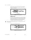
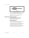
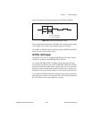
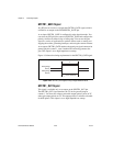
Figure 4-34 shows the timing requirements for the GPCTR1_GATE signal.
Figure 4-34. GPCTR1_GATE Signal Timing in Edge-Detection Mode
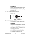
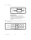
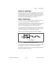
GPCTR1_OUT Signal
This signal is available only as an output on the GPCTR1_OUT pin.
The GPCTR1_OUT signal monitors the TC device general-purpose
counter 1. You have two software-selectable output options: pulse on TC
and toggle output polarity on TC. The output polarity is software-selectable
for both options. This output is set to high-impedance at startup.
Rising-Edge
Polarity
Falling-Edge
Polarity
t
w
= 10 ns minimum
t
w