


cFP-RLY-421 2 ni.com
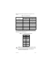
Before you configure a FieldPoint system that uses a cFP-RLY-421
module, calculate the total power consumption of the I/O modules
on the FieldPoint bank. You can find the power requirement
specification in the operating instructions for each I/O module.
The maximum power the network module can supply is specified
in the network module user manual. Make sure the total power
requirement for all of the I/O modules in the bank is less than the
maximum power available from the network module.
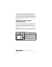
Suppose you have a bank with a cFP-2000 network module,
four cFP-RLY-421 modules, and four cFP-DI-301 modules. The
cFP-2000 can supply up to 9 W. The cFP-RLY-421 requires 1.7 W,
and cFP-DI-301 requires 0.325 W. The four cFP-RLY-421 and four
cFP-DI-301 modules require a total of 8.1 W:
4 × 1.7 W + 4 × 0.325 W = 8.1 W
This configuration meets the 9 W power requirement.
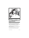
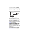
Installing the cFP-RLY-421
The cFP-RLY-421 mounts on a Compact FieldPoint backplane
(cFP-BP-x), which provides operating power to the module.
Installing the cFP-RLY-421 onto a powered backplane does not
disrupt the operation of the bank.
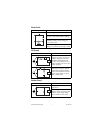
To install the cFP-RLY-421, refer to Figure 1 and complete the
following steps:
1. Align the captive screws on the cFP-RLY-421 with the holes
on the backplane. The alignment keys on the cFP-RLY-421
prevent backward insertion.
2. Press firmly to seat the cFP-RLY-421 on the backplane.
3. Using a number 2 Phillips screwdriver with a shank of at least
64 mm (2.5 in.) length, tighten the captive screws to 1.1 N ⋅ m
(10 lb ⋅ in.) of torque. The nylon coating on the screws prevents
them from loosening.