


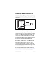

cFP-RLY-421 6 ni.com
In addition, the cFP-RLY-421 has internal protection MOVs to
prevent excessively high voltage from being applied across the
contacts. The MOVs are located between the NO and IC contacts
of each relay. However, National Instruments still recommends the
use of a protection circuit across an inductive load. The flyback
protection causes a small leakage current, which is detailed in the
Specifications section.
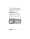
Guidelines for Selecting Contact
Protection Circuits
1
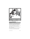
Proper selection is critical, as the use of a contact-protection device
can extend contact life. When mounting the protection device,
always locate it near the immediate area of the load or contact.
Typically, you should mount a protective device within 18 in. of the
load or contact.
Typically, contact-protection circuits are provided for an overview,
but you should thoroughly examine the circuit you are planning
to use.
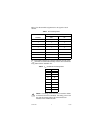
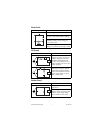
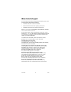
Diode and Zener Diode Circuit
1
This section has been reprinted with permission from American Zettler, Inc.
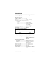
Diagram Notes
Use in DC applications only.
Use when diode circuit causes too long
release time.
Use zener diode with zener voltage about
equal to power supply voltage.
Load