


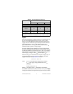
© National Instruments Corp. 13 FP-CTR-502 and cFP-CTR-502
Application Note:
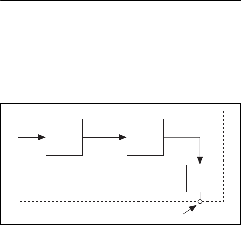
Generating a Continuous Pulse Train
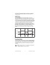
You can use two [c]FP-CTR-502 count-input channels and one
output channel to generate a continuous pulse train with a
controllable duty cycle and period. The first count-input channel
serves as a clock prescaler and divides the input clock by a fixed
value. This generates a slower clock for the second count-input
channel, which serves as the pulse counter. The pulse counter is the
output source for the output channel.
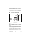
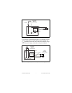
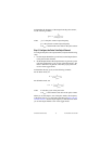
Figure 11 shows the components of a continuous pulse train.
Figure 11. Continuous Pulse Train
Step 1. Set Up the Prescaler Counter
To set up the prescaler counter, complete the following steps:
1. If you do not need to scale the frequency of your clock input,
you can configure the pulse counter to use the clock input
directly instead of the prescaler counter. To set up the pulse
counter, skip to Step 2. Set Up the Pulse Counter.
2. Select two count-input channels and an output channel to use.
Select count-input channels that are numbered sequentially
(for example, Channels 1 and 2, 5 and 6, or 7 and 0). The
count-input channel with the lower number is the prescaler
counter and the count-input channel with the higher number is
the pulse counter.
3. Set the Gate Source attribute of the prescaler counter to
Always Enabled, and set Read Reset Mode to Don’t Reset
On Read.
Clock
Input
Prescaler
Counter
n
Pulse
Counter
n
+ 1
Internal
Connection
Internal
Connection
Output
Pulse Output Terminal
[c]FP-CTR-502