


© National Instruments Corp. 5 FP-CTR-502 and cFP-CTR-502
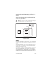
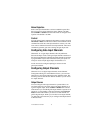
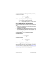
Inputs
Each input channel has one input terminal, V
IN
. Each channel also
has V
SUP
and COM terminals that can supply power to field
devices or provide additional connections to the external power
supply. You can connect the eight count-input channels and four
gate-input channels to devices with sinking outputs. The
[c]FP-CTR-502 has sourcing inputs, which means that the V
IN
terminal provides a path to a voltage supply.
The [c]FP-CTR-502 input channels are optically isolated from
the rest of the FieldPoint bank and have current-limiting circuitry.
All the input channels are referenced to the V and V
SUP
terminals.
In the ON state, an optoisolator is turned on between the positive
external supply voltage (V and V
SUP
) and the input (V
IN
).
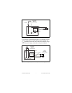
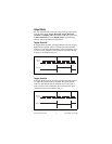
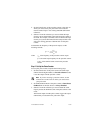
When choosing your external devices and power supply, keep in
mind that the input-logic thresholds are defined by the power
supply as detailed in the Specifications section.
V
threshold
= V
SUP
– V
K
where V
threshold
is the threshold voltage for the channel
V
SUP
is the supply voltage, measured across V
SUP
and COM
V
K
has a value of 2–3 V
When V
IN
, the voltage across V
IN
and COM, is lower than V
threshold
,
the channel is ON. Therefore, if you connect a 24 V power supply
to the [c]FP-CTR-502, an input channel registers an ON state when
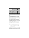
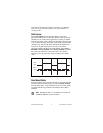
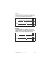
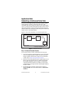
Outputs
Output 0 13 29 30
Output 1 14 29 30
Output 2 15 31 32
Output 3 16 31 32
1
Install a 1 A maximum, fast-acting fuse on each V
OUT
terminal.
2
Install a 2 A maximum, fast-acting fuse on each V and V
SUP
terminal.
Table 1. Terminal Assignments (Continued)
Channel Name
Terminal Numbers
V
IN
or V
OUT
1
V
SUP
2
COM