


FP-PWM-520 and cFP-PWM-520 12 ni.com
Specifications
The following specifications are typical for a range of –40 to 70 °C
unless otherwise noted.
Output Characteristics
Number of channels..........................8
Output type .......................................Sourcing
Output voltage ..................................Supply voltage – (Output
current × Output impedance)
Supply voltage..................................5 VDC or 10 to 30 VDC,
user-provided
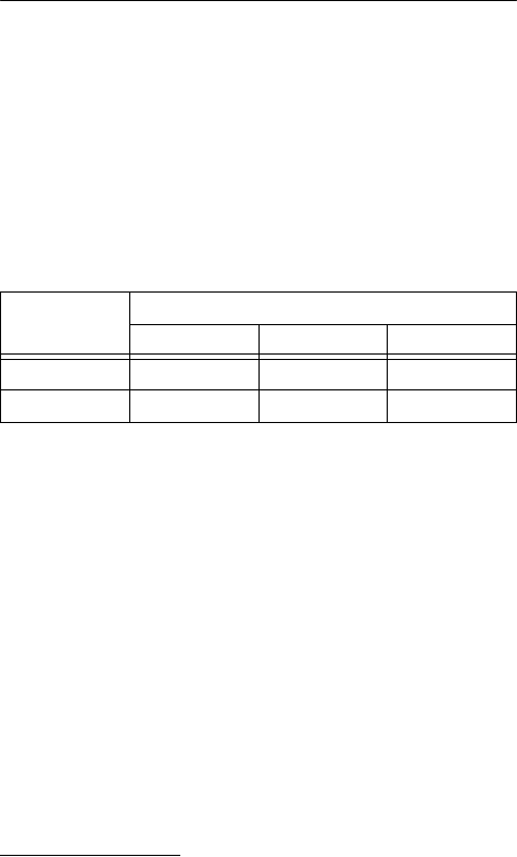
Maximum output current per channel
ON resistance
Revision E and later modules
1
...0.15 Ω
Revision D and earlier
modules ......................................0.3 Ω
Pulse-width accuracy........................–1, +3 μs, any period and
duty cycle
Short-Circuit Protection
Minimum trip current
Revision E and later modules.....9 A
Revision D and earlier
modules ......................................1 A
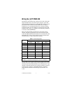
Module
Temperature Ranges
–40to50°C 50 to 60 °C 60 to 70 °C
cFP-PWM-520 1 A 0.75 A 0.5 A
FP-PWM-520 1 A 1 A 1 A
1
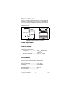
The letter in the part number identifies the revision of the module. For example, part
number 185715A-02 identifies a revision A cFP-PWM-520. The part number is
printed on a label on the module. On the FP-PWM-520, the label is on the bottom of
the module. On the cFP-PWM-520, the label is on the back of the module.