


FP-PWM-520 and cFP-PWM-520 2 ni.com
Installing the FP-PWM-520
The FP-PWM-520 mounts on a FieldPoint terminal base
(FP-TB-x), which provides operating power to the module.
Installing the FP-PWM-520 onto a powered terminal base does
not disrupt the operation of the bank.
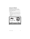
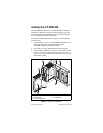
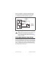
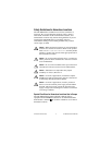
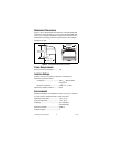
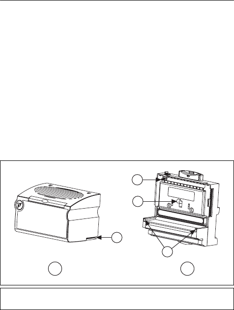
To install the FP-PWM-520, refer to Figure 1 and complete the
following steps:
1. Slide the terminal base key to either position X, used for any
module, or position 4, used for the FP-PWM-520 module.
2. Align the FP-PWM-520 alignment slots with the guide rails on
the terminal base.
3. Press firmly to seat the FP-PWM-520 on the terminal base.
When the module is firmly seated, the terminal base latch locks
it into place.
Figure 1. Installing the FP-PWM-520
1 I/O Module
2 Terminal Base
3 Alignment Slot
4 Terminal Base Key
5 Latch
6 Guide Rails
1
3
2
4
5
6