


Chapter 4 Signal Connections
IMAQ PCI/PXI-1411 User Manual 4-2 www.ni.com
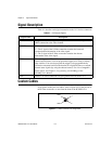
Signal Description
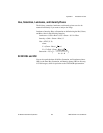
Table 4-1 describes each signal connection on the 1411 device connectors:
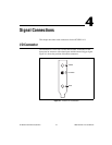
Custom Cables
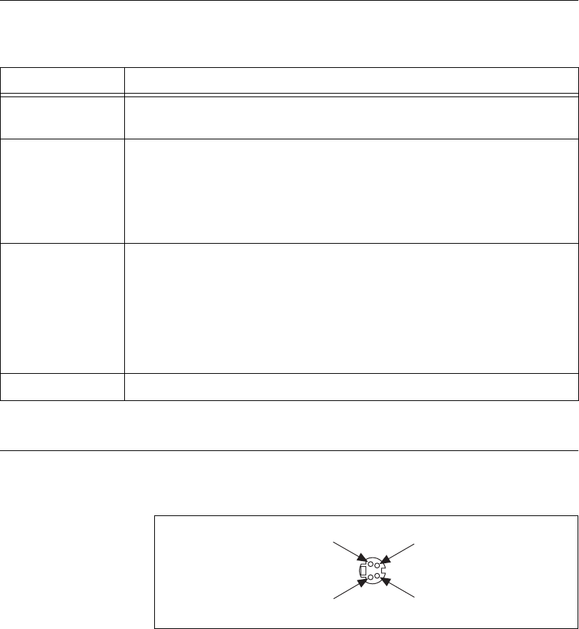
If you plan to make your own cables, refer to Figure 4-2 for the pin-out of
the S-Video connector, as seen from the front of the PCI/PXI-1411.
Figure 4-2.
S-Video Connector Pin Assignments
Table 4-1.
I/O Connector Signals
Signal Name Description
VIDEO Composite Video—The signal allows you to make a referenced single-ended
(RSE) connection to the video channel.
S-VIDEO S-Video—A connector composed of two signals, as follows:
Y—The Y signal of the S-Video connection contains the luma and
synchronization information of the video signal.
C—The C signal of the S-Video connection contains the chroma
information of the video signal.
TRIG External trigger—A TTL I/O line you can use to start an acquisition or to
control external events. You can program the triggers to be rising or falling
edge sensitive. You can also program the triggers to be programmatically
asserted or unasserted similar to the function of a digital I/O line or to contain
internal status signals (by using the onboard events). For a list of mappable
status signals, see Chapter 3, Programming with NI-IMAQ, of the
NI-IMAQ User Manual.
GND Ground—A direct connection to digital ground on the PCI/PXI-1411.
GND
C
Y
GND