


Chapter 3 Signal Connections
© National Instruments Corporation 3-7 6527 User Manual
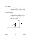
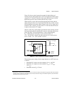
Isolation Voltages
The positive and negative (DIG+ and DIG–) terminals of each channel are
isolated from the other input and output channels, from the +5 V and GND
pins, and from the computer power supply. Isolation barriers provide
isolation up to 60 VDC or 30 VAC (42 V peak) between any two terminals,
except between the two terminals making up a single digital I/O channel.
Do not exceed 60 VDC or 30 VAC between any two terminals of the 6527
device, including:
• any two digital I/O (DIG+ or DIG–) lines of separate channels
• any DIG+ or DIG– line and the GND or +5 V lines
• the DIG+ line and the DIG– line of any output channel
Do not exceed 28 VDC or apply any negative or AC voltage between the
DIG+ and DIG– terminals of any input channel.
Warning
You must not exceed the isolation voltage limits. Exceeding the voltage limits
can lead to injury. National Instruments is not liable for any damages resulting from signal
connections that exceed these limits.
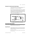
Optically Isolated Inputs
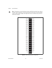
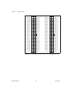
On a 6527 device, I/O connector pins 1 through 48, shown in Figure 3-1,
represent the optically isolated input signal pins.
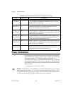
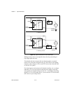
Input Channels
The optically isolated inputs of a 6527 device contain a light-emitting
diode (LED), a resistor for current limiting, and digital filtering and
change-detection circuitry. The 6527 boards offer 24 channels of isolated
digital input. Each channel has its own positive and negative terminals.
Always apply the higher voltage, if any, to the positive terminal. The
maximum input voltage (V
IN
) on these channels is +28 VDC.
Caution
Never apply a voltage to the positive (DIG+) terminal of any input channel that is
lower than the voltage on the channel’s negative (DIG–) terminal. National Instruments is
not liable for any damages resulting from incorrect signal connection.