


Chapter 4 Device Overview
6527 User Manual 4-4 www.ni.com
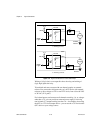
You can enable filtering on as many input lines as you wish. All filtered
lines share the same timing interval. The interval ranges from 100 ns to
100 ms. However, as shown in Table 4-1, an interval of 200 µs or less does
not guarantee blocking of high pulses. Therefore, an interval greater than
200 µs is recommended.
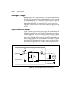
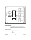
Internally, the filter uses two clocks. The first, a sample clock, has a 100 ns
period. The second, a filter clock, is generated by a counter and has a period
equal to one half your specified timing interval. The input signal from the
optocoupler is sampled on each rising edge of the sample clock— every
100 ns. However, a change in the input signal is recognized only if it
maintains its new state for at least two consecutive rising edges of the filter
clock.
The two clocks serve different functions. The filter clock, which is
programmable, lets you control how long a pulse must last to be
recognized. The sample clock provides a fast sample rate to ensure that
input pulses remain constant between filter clocks.
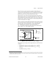
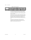
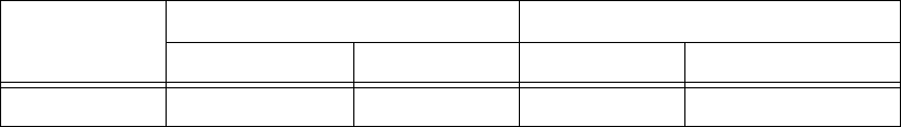
Table 4-1. Digital Filter Characteristics
Filter Interval
Pulse Width Passed Pulse Width Blocked
Low Pulse High Pulse Low Pulse High Pulse
t
interval
t
interval
+ 100 µs t
interval
t
interval
/2 (t
interval
/2) – 100 µs