


Index
© National Instruments Corporation I-3 NI 2590/2591 User Manual
S
safety instructions, 2-1
scanner advanced trigger
modes of operation, 2-8
overview, 1-1
purpose and use, 2-7
scanning
common questions, C-1 to C-2
initiating, 2-8
random scanning, 2-6 to 2-7
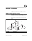
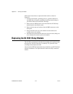
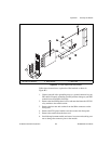
servicing the NI 2590/2591, B-1 to B-3
parts locator diagram
NI 2590, B-1
NI 2591, B-3
replacing relay module
NI 2590, B-1 to B-2
NI 2591, B-2 to B-3
signal descriptions for front connector
(table), 1-4
software choices, 1-5 to 1-6
National Instruments application
software, 1-5
NI-Switch instrument driver, 1-5
third-party software, 1-6
specifications, A-1 to A-6
certification and compliances
NI 2590, A-3
NI 2591, A-6
dynamic characteristics
NI 2590, A-2
NI 2591, A-5
environment
NI 2590, A-3
NI 2591, A-5 to A-6
input characteristics
NI 2590, A-1
NI 2591, A-4
physical
NI 2590, A-3
NI 2591, A-5
power requirement
NI 2590, A-3
NI 2591, A-5
PXI bus interface, A-2
PXI trigger bus, A-3
RF performance characteristics
NI 2590, A-1 to A-2
NI 2591, A-4 to A-5
switch control circuitry, 2-6
switches do not switch, C-1
system integration, by National
Instruments, D-1
T
technical support resources, D-1 to D-2
third-party software, 1-6
triggering, multiboard, 2-8 to 2-9
triggers. See PXI triggers.
W
Web support from National Instruments, D-1
Worldwide technical support, D-2