


© National Instruments Corporation 1-1 NI 2590/2591 User Manual
1
Routing Signals
with Your NI 2590/2591
This manual describes the electrical and mechanical characteristics of the
NI 2590, a 1 × 4, 50 Ω, 1.3 GHz multiplexer module, and the NI 2591,
a1× 4, 50 Ω, 4.0 GHz multiplexer module, for the PXI bus. It contains
information concerning their installation and operation.
About the NI 2590/2591
This section summarizes the features and operation of the NI 2590/2591
switch module; refer to Chapter 2, NI 2590/2591 Operation,formore
complete details. In addition, refer to Appendix A, Specifications,
for detailed specifications of the switch module.
The NI 2590/2591 are general-purpose, 4-channel, high-bandwidth
multiplexing switches.
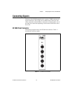
The NI 2590 uses single-pole double-throw high-bandwidth relays capable
of switching signals from DC to 1.3 GHz. The characteristic impedance of
the channels is 50 Ω. The maximum rated voltage of the switch is 24 VDC,
and the maximum rated current is 1 ADC.
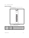
The NI 2591 uses a self-contained relay module consisting of three
high-bandwidth relays capableof switching signals from DCto 4 GHz.The
characteristic impedance of the channels is 50 Ω. The maximum rated DC
voltage of the module is 30 V. The maximum rated current is 0.33 A.
Triggers
Two triggers are used for handshaking between the NI 2590/2591 switches
and other PXI instruments. The scanner advanced trigger indicates when
the module has closed all the necessary switches for the next scan and the
switches have settled, or debounced.