Chapter 2 Hardware Overview
NI 5911 User Manual 2-4 ni.com
Input Bias
The inputs of the PGIA typically draw an input bias current of 1 nA at
25 °C. Attaching a device with a very high source impedance can cause
an offset voltage to be added to the signal you measure, according to
the formula R
s
×1nA,whereR
s
is the external source impedance. For
example, if the device you have attached to the NI 5911 has an output
impedance of 10 kΩ, typically the offset voltage is 10 µV (10 kΩ ×1nA).
Input Protection
The NI 5911 features input-protection circuits that protect both the positive
and negative analog input from damage from AC and DC signals up to
±42 V.
If the voltage at one of these inputs exceeds a threshold voltage, V
tr
,the
input clamps to V
tr
and a resistance of 100 kΩ is inserted in the path to
minimize input currents to a nonharmful level.
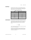
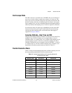
The protection voltage, V
tr
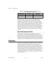
,is input range dependent, as shown in Table 2-1.
AC Coupling
When you need to measure a small AC signal on top of a large DC
component, you can use AC coupling. AC coupling rejects any DC
component in your signal before it enters into the PGIA. Activating AC
coupling inserts a capacitor in series with the input impedance. Input
coupling can be selected via software. See Appendix B, Digitizer Basics,
for more information on input coupling.
Oscilloscope and Flexible Resolution Modes
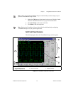
In oscilloscope mode, the NI 5911 works as a conventional desktop
oscilloscope, acquiring data at 100 MS/s with a vertical resolution of 8 bits.
This mode is useful for displaying waveforms and for deriving waveform
parameters such as slew rate, rise time, and settling time.
Flexible resolution differs from oscilloscope mode in two ways: it has
higher resolution (sampling rate dependent), and the signal bandwidth is
limited to provide antialiasing protection. This mode is useful for spectral
analysis, distortion analysis, and other measurements for which high
resolution is crucial.


