


Appendix B Digitizer Basics
© National Instruments Corporation B-7 NI 5911 User Manual
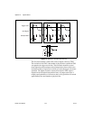
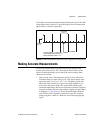
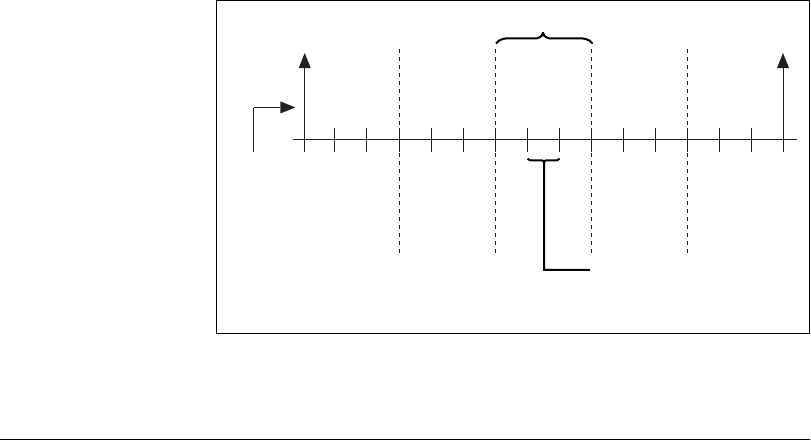
For example, consider themaximum interpolation factor tobe 5. Ifthe TDC
could output values from 0 to 15, then each logical bin will contain three
physical bins, as shown in Figure B-6.
FigureB-6.
RelationshipbetweenInterpolationFactor, LogicalBins,andPhysicalBins
Making Accurate Measurements
For accurate measurements, you should use the right settings when
acquiring data with your NI 5911. Knowing the characteristics of the
signal in consideration helps you to choose the correct settings. Such
characteristics include:
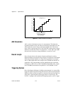
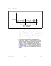
• Peak-to-peak value—This parameter, in units of volts, reflects the
maximum change in signal voltage. If V is the signal voltage at any
given time, then V
pk-to-pk
=V
max
–V
min
. The peak-to-peak value
affects the vertical sensitivity or gain of the input amplifier. If you
do not know the peak-to-peak value, start with the smallest gain
(maximum input range) and increase it until the waveform is digitized
using the maximum dynamic range without clipping the signal. Refer
to Appendix A, Specifications, for the maximum input voltage for
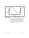
your NI 5911 device. Figure B-7 shows that a gain of 5 is the best
setting to digitize a 300 mV, 1 MHz sine wave without clipping the
signal.
Physical Bin
3 Physical Bins = 1 Logical Bin
Desired Interpolation Factor = 5
Max Interpolation Factor = 15
Sample
Clock
Logical Bin