


Chapter 4 Connecting Signals
© National Instruments Corporation 4-27 NI 6013/6014 User Manual
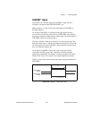
CONVERT* Signal
Any PFI pin can externally input the CONVERT* signal, which is
available as an output on the PFI2/CONVERT* pin.
Refer to Figures 4-11 and 4-12 for the relationship of CONVERT* to
the DAQ sequence.
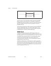
As an input, CONVERT* is configured in the edge-detection mode.
You can select any PFI pin as the source for CONVERT* and configure
the polarity selection for either rising or falling edge. The selected edge of
CONVERT* initiates an A/D conversion.
The ADC switches to hold mode within 60 ns of the selected edge. This
hold-mode delay time is a function of temperature and does not vary from
one conversion to the next. CONVERT* pulses should be separated by at
least 5 µs (200 kHz sample rate).
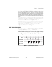
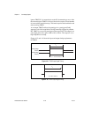
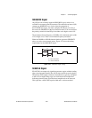
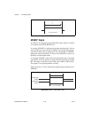
As an output, CONVERT* reflects the actual convert pulse that is
connected to the ADC, even if the conversions are being externally
generated by another PFI. The output is an active low pulse with a pulse
width of 50 to 150 ns. This output is set to high-impedance at startup.
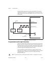
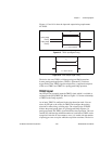
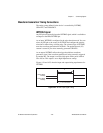
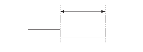
Figures 4-19 and 4-20 show the input and output timing requirements for
CONVERT*.
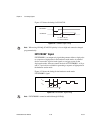
Figure 4-19. CONVERT* Input Signal Timing
Rising-Edge
Polarity
Falling-Edge
Polarity
t
w
= 10 ns minimum
t
w