


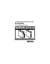

© National Instruments Corp. 9 NI 9472/9474
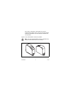
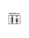
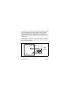
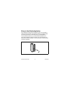
The NI 9472/9474 with screw terminal has a 10-terminal,
detachable screw-terminal connector. The NI 9472 with DSUB has
a 25-pin DSUB connector. Each channel of the NI 9472/9474 has
a terminal or pin, DO, to which you can connect a device. The
eight digital output channels are internally referenced to the
common terminal or pin, COM. National Instruments recommends
you provide independent COM and V
sup
wiring for each channel of
the NI 9472 with DSUB to minimize current flow in the COM and
V
sup
wiring. The COM pins on the NI 9472 with DSUB are
internally connected..
Note You must use 2-wire ferrules to create a secure
connection when connecting more than one wire to a
single terminal on the NI 9472/9474 with screw terminal.
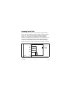
Each channel has an LED that indicates the state of the channel.
When a channel LED is lit, the channel is on. When the LED is
dark, the channel is off. The LEDs are disabled when the chassis is
in sleep mode. Refer to the Sleep Mode section for more
information about sleep mode.