


NI cDAQ-9172 User Guide and Specifications 56 ni.com
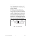
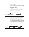
Counter n Source Signal
The selected edge of the Counter n Source signal increments and
decrements the counter value, depending upon the application the counter
is performing. Table 6 lists how this terminal is used in various
applications.
Routing a Signal to Counter n Source
Each counter has independent input selectors for the Counter n Source
signal. You can route the following signals to the Counter n Source input:
•80MHz Timebase
•20MHz Timebase
• 100 kHz Timebase
• Any PFI terminal
• Analog Comparison Event
In addition, you can route Counter 1 TC or Counter 1 Gate to
Counter 0 Source. You can also route Counter 0 TC or Counter 0 Gate to
Counter 1 Source.
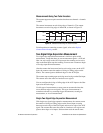
Routing Counter n Source to an Output Terminal
You can route Counter n Source to any output PFI terminal.
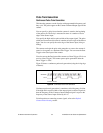
Counter n Gate Signal
The Counter n Gate signal can perform many different operations
depending on the application including starting and stopping the counter,
and saving the counter contents.
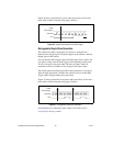
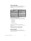
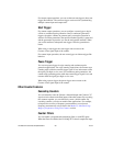
Table 6. Counter Applications and Counter n Source
Application Purpose of Source Terminal
Pulse Generation Counter Timebase
One Counter Time Measurements Counter Timebase
Two Counter Time Measurements Input Terminal
Nonbuffered Edge Counting Input Terminal
Buffered Edge Counting Input Terminal
Two-Edge Separation Counter Timebase