


© National Instruments Corporation 7 Getting Started with the NI 7811R
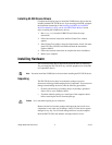
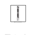
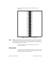
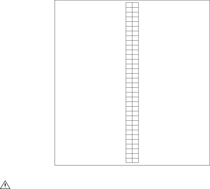
Figure 2 shows the pin assignments for all I/O connectors on the
PXI-7811R.
Figure 2. PXI-7811R I/O Connector Pin Assignments
Caution
Connections that exceed any of the maximum ratings of input or output signals
on the PXI-7811R can damage the PXI-7811R and the computer. NI is not liable for any
damage resulting from such signal connections. Refer to the PXI-7811R User Manual for
the maximum input ratings for each signal.
For detailed information about connecting I/O signals, refer to the
NI 7811R User Manual.
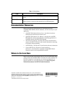
Cabling Options
Accessing the signals on the I/O connectors requires at least one cable and
one signal accessory. Table 1 summarizes the National Instruments cables
available for use with the NI 7811R device.
DGND
DGND
DGND
DGND
DGND
DGND
DGND
DGND
DGND
DGND
DGND
DGND
DGND
DGND
DGND
DGND
DGND
DGND
DGND
DGND
DGND
DGND
DGND
DGND
DGND
DGND
+5V
+5V
DIO28
DIO30
DIO32
DIO34
DIO36
DIO38
DIO0
DIO2
DIO3
DIO5
DIO6
DIO7
DIO8
DIO1
DIO4
DIO9
DIO10
DIO11
DIO12
DIO13
DIO14
DIO15
DIO16
DIO17
DIO18
DIO19
DIO20
DIO21
DIO22
DIO23
DIO24
DIO25
DIO26
DIO27
DIO29
DIO31
DIO33
DIO35
DIO37
DIO39
135
236
337
438
539
640
741
842
943
10 44
11 45
12 46
13 47
14 48
15 49
16 50
17 51
18 52
19 53
20 54
21 55
22 56
23 57
24 58
25 59
26 60
27 61
28 62
29 63
30 64
31 65
32 66
33 67
34 68