


© National Instruments Corporation 5 NI TB-2709 Installation Guide
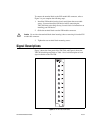
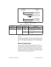
Figure 4. NI TB-2709 Block Diagram
For more detailed descriptions of these signals, refer to the S Series User
Manual.
Additional signal configuration information is available in Measurement &
Automation Explorer (MAX). To access this information in MAX, select
your device under Devices and Interfaces, and click the Device Routes
tab.
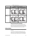
Measuring Floating Signals
You can use the TB-2709 to measure floating and ground-referenced
analog input signals. To measure floating signal sources, move the switch
located under the rubber-sealed door on the enclosure cover for the AI
channel you are using to the ON (floating source) switch position. In the
floating source switch position, the amplifier negative terminal connects to
ground through a 5 kΩ resistor in parallel with a 0.1
μF capacitor. Table 2
shows the TB-2709 switch configuration options.
Table 1. TB-2709 Signal Descriptions
Signal Name Reference Direction Description
AI <0..7> AI GND Input Analog Input channels 0 through 7.
PFI 0/AI Start Trig D GND Input As an input, this pin is a programmable
function input (PFI).
Output As an output, this pin is the AI Start
Trigger signal.
AI <0..7> +
AI <0..7> –
Front Panel
SMB Connectors
DAQ Device
Signals
AI <0..7> GND
AI Start Trig
D GND
5 kΩ
0.1 μF