


© National Instruments Corporation 13 NI USB-9215 Series User Guide and Specifications
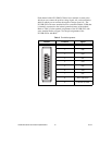
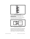
Figure 7. BNC Connector Assignments
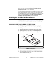
Connecting Differential Voltage Signals to the
NI USB-9215 Series
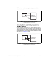
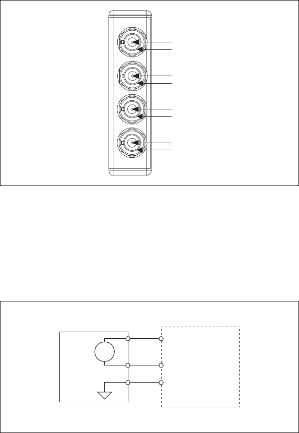
For grounded differential signals, connect the positive voltage signal to
AI+ and the negative signal to AI–. For the NI USB-9215 with screw
terminal, connect the signal reference to the COM terminal.
Figure 8. Connecting a Grounded Differential Voltage Signal to the NI USB-9215
(NI USB-9215 with Screw Terminal Shown)
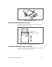
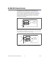
For floating differential signals, the voltage source may go outside of the
common-mode signal range of the NI USB-9215 with screw terminal. If the
voltage source is outside of the common-mode range, data read by the
NI USB-9215 is not accurate. To keep the voltage source within the
common-mode range, connect the negative lead of the signal to COM
through a 1 MΩ resistor, as shown in Figure 9. The NI USB-9215A with
AI3+
AI3–
AI2+
AI2–
AI0+
AI0–
AI1+
AI1–
AI–
AI+
+
–
COM
NI USB-9215 with
Screw Terminal
Voltage
Source