Chapter 4 Signal Connections
PCI-4451/4452 User Manual 4-12
©
National Instruments Corporation
terminals is still equal to the desired signal. If the minus side is grounded,
the plus voltage is equal to the signal. Conversely, if the plus side is
grounded, the minus voltage is equal to the negative of the signal. In all
cases, the difference is equal to the signal.
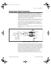
Connection of analog output signals from your PCI-4451 device depends
on the configuration of the devices receiving the signals. For most signals,
you use a DIFF configuration and simply connect +DACxOUT (where x is
the PCI-4451 channel) to the signal and −DACxOUT to the signal ground
(or signal minus, as appropriate). When driving some floating devices,
however, you may sometimes find it helpful to use the SE configuration and
connect the floating ground system of the device to AOGND to reduce
common-mode noise coupled from an interfering source to the device.You
can make DIFF and SE connections through the BNC-2140 accessory.
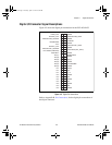
Analog Power Connections
Two pins on the analog I/O connector supply +5 V from the computer
power supply via a self-resetting fuse. The fuse will reset automatically
within a few seconds after the overcurrent condition is removed. These pins
are referenced to DGND and you can use them to power external analog
accessories like the BNC-2140.
• Power rating +4.65 to +5.25 VDC at 0.5 A
Caution
Do not under any circumstances connect these +5 V power pins directly to analog
ground, digital ground, or to any other voltage source on the PCI-4451/4452
device or any other device. Doing so can damage the PCI-4451/4452 device and
the computer. National Instruments is not liable for damages resulting from such
a connection.
Digital I/O Signal Connections
The digital I/O signals are DIO<0..7> and DGND. DIO<0..7> are the
signals making up the DIO port. DGND is the ground-reference signal for
the DIO port. You can program all lines individually to be inputs or outputs.
!
User.book Page 12 Tuesday, April 14, 1998 10:20 AM


