


© National Instruments Corporation 13 SCC-AI Series Isolated Analog Input Modules User Guide
SCC-AI Module Pin Assignments
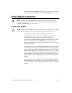
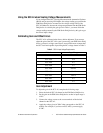
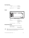
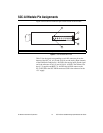
Figure 5 shows the I/O connector pins on the bottom of the module.
Figure 5. SCC Module Bottom View
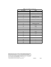
Table 3 lists the signal corresponding to each I/O connector pin on the
bottom of the SCC-AI. AI (X) and AI (X+8) are the analog input channels
of the E/M Series DAQ device. AI GND is the analog input ground signal
and is the reference for AI (X) and AI (X+8). A GND is the reference for
the ±15 V supplies and REF 5 V. AI GND and A GND connect to the
SC-2345/2350 at the SCC-PWR connector. GND is the reference for the
+5V supply.
1Pin 1 2Pin 2 3 PWB Key 4 Pin 19 5Pin 20
5
4
2
1
3