


© National Instruments Corporation 5 SCC-AI Series Isolated Analog Input Modules User Guide
Connecting the Input Signals
Note The signal names have changed. Refer to ni.com/info and enter rdtntg to
confirm the signal names.
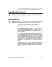
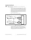
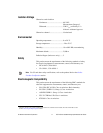
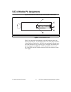
Each screw terminal on the SCC-AI is labeled by pin number <1..4>. Pins 1
and 2 form a channel routed to E/M Series DAQ device channel X+8, and
pins 3 and 4 form a channel routed to the E/M Series DAQ device channel
X, where X is 0 to 7 depending on the socket where you plug in the module.
The SCC-AI provides channel-to-ground and module-to-module isolation
only. It does not provide isolation between the two channels of the SCC-AI.
Because both channels must have the same reference voltage, pins 1 and 3
are connected together internally.
Figure 1 shows the SCC-AI signal connections.
Figure 1. SCC-AI Signal Connections
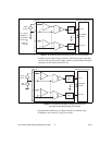
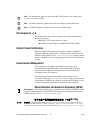
The inputs are designed in a floating (nonreferenced) single-ended
configuration. If the measured signals are floating, connect the negative
input pins, 1 and 3, to AI SENSE on the SC-2345/2350 terminal block or
AI GND on the SC-68, through a 10 kΩ to 100 kΩ resistor. Figure 2 shows
a floating signal connection on one channel of the SCC-AI.
+
4
Lowpass
Filter
+
–
–
+
–
+
–
Lowpass
Filter
3
2
1
E/M Series DAQ Device
Signal
Source
AI (X )
SCC-AI
AI SENSE
AI GND
AI (X+8)