


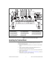

© National Instruments Corporation 13 SCXI-1321 Terminal Block Installation Guide
z is the module slot of the SCXI-1121
w is the channel of the module that you want to engage the shunt and
take measurements
For example, if you want to measure the voltage at channel 0 with the shunt
resistor enabled, use the SCXI channel string
ob0 ! sc1 ! md1 ! shunt0.
You also can specify a list of channels by using
ob0 ! sc1 ! md1 ! shunt0:
w
, for example. Refer to the LabVIEW
Measurements Manual for information on using SCXI channel strings.
The shunting resistors R
SCAL
are socketed so that you can replace them with
a resistor of another value to achieve the required nulling range for your
application. The sockets and corresponding channels are shown in Table
3.
The factory installed R
SCAL
provided on the terminal block have a 301 kΩ
±1% value.
Assuming a quarter-bridge strain-gauge configuration with a gauge factor
of GF = 2, the equivalent strain change introduced by the R
SCAL
shunting
resistor is –199 µε.
Refer to the Traditional NI-DAQ User Manual for more information on
strain-gauge bridge configurations and formulas.
Use the following formula to determine the change due to this shunting
resistor:
Next, using the appropriate strain-gauge strain formula, and assuming that
you have no static voltage, determine the equivalent strain the R
SCAL
should
provide. For example, R
SCAL
= 301 kΩ and a quarter-bridge 120 Ω strain
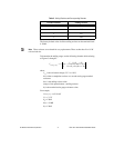
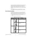
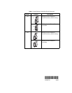
Table 3. Socket to Channel Relationship
Channel Shunt Resistor Socket
0 R4
1 R6
2 R8
3 R10
V
change
V
ex
R
d
R
SCAL
R
g
+()
R
g
R
SCAL
R
d
R
SCAL
R
g
+()+
-----------------------------------------------------------------
V
ex
2
-------–=