


© National Instruments Corporation 5 SCXI-1321 Terminal Block Installation Guide
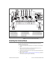
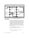
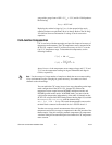
Figure 2. SCXI-1321 Circuit Parts Locator Diagram
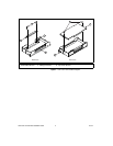
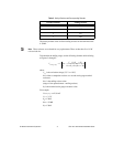
Installing the Terminal Block
To connect the terminal block to the SCXI module front connector,
complete the following steps:
1. Connect the module front connector to its connector on the terminal
block.
2. Make sure that the module top and bottom thumbscrews do not
obstruct the rear panel of the terminal block.
3. Tighten the top and bottom screws on the back of the terminal block to
hold it securely in place.
4. Refer to the Performed or Supported Signal Conditioning section for
information on specific signal conditioning.
1 Screw Terminals
2 Product Information
3 W1 (CH0 Null Enabled)
4 W2 (CH1 Null Enabled)
5 R3 (CH0 Null Resistor)
6 R4 (CH0 Shunt Resistor)
7 R5 (CH1 Null Resistor)
8 R6 (CH1 Shunt Resistor)
9 R7 (CH2 Null Resistor)
10 R8 (CH2 Shunt Resistor)
11 R9 (CH3 Null Resistor)
12 R10 (CH3 Shunt Resistor)
13 W5 (CJC Mode)
14 Warning Label
15 W4 CH3 Null Enabled)
16 W3 (CH2 Null Enabled)
17 R15 (CH3 Null Potentiometer)
18 R14 (CH2 Null Potentiometer)
19 R2 (CH1 Null Potentiometer)
20 R1 (CH0 Null Potentiometer)
Note: R3 through R10 are socketed.
1
2
3 4
7 12
13
14
15
16
17181920
5 6 8 9 10 11