


USB-6008/6009 User Guide and Specifications 12 ni.com
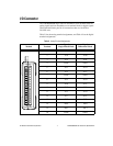
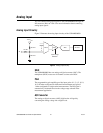
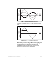
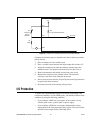
Figure 7. Example of a Differential 20 V Measurement
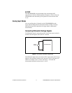
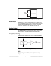
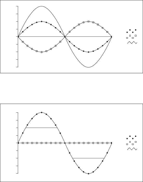
Connecting a signal greater than ±10 V on either pin results in a clipped
output.
Figure 8. Exceeding +10 V on AI Returns Clipped Output
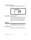
Connecting Reference Single-Ended Voltage Signals
To connect reference single-ended voltage signals (RSE) to the
USB-6008/6009, connect the positive voltage signal to the desired
AI terminal, and the ground signal to a GND terminal.
–5
–10
–15
–20
20
15
10
5
0
Amplitude (V)
AI 1
AI 5
Result
–5
–10
–15
–20
20
15
10
5
0
Amplitude (V)
AI 1
AI 5
Result