


USB-6008/6009 User Guide and Specifications 16 ni.com
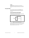
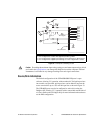
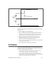
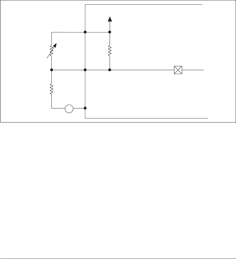
Figure 13. Example of Connecting External User-Provided Resistor
Complete the following steps to determine the value of the user-provided
pull-up resistor:
1. Place an ammeter in series with the load.
2. Place a variable resistor between the digital output line and the +5 V.
3. Adjust the variable resistor until the ammeter current reads as the
intended current. The intended current must be less than 8.5 mA.
4. Remove the ammeter and variable resistor from your circuit.
5. Measure the resistance of the variable resistor. The measured
resistance is the ideal value of the pull-up resistor.
6. Select a static resistor value for your pull-up resistor that is greater than
or equal to the ideal resistance.
7. Re-connect the load circuit and the pull-up resistor.
I/O Protection
To protect the USB-6008/6009 against overvoltage, undervoltage, and
overcurrent conditions, as well as ESD events, you should avoid these fault
conditions by using the following guidelines:
• If you configure a DIO line as an output, do not connect it to any
external signal source, ground signal, or power supply.
• If you configure a DIO line as an output, understand the current
requirements of the load connected to these signals. Do not exceed the
specified current output limits of the DAQ device.
GND
P0.0
+5 V
Rp
Re
Rl
Port Pad
USB-6008/6009
4.7 KΩ Onboard Resistor
External
Pull-up
Resistor
Load
A
+5 V