USB-6501 OEM User Guide 4 ni.com
Signal Descriptions
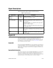
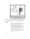
Table 2 describes the signals available on the I/O connectors.
Digital I/O
The USB-6501 OEM has 24 single-ended digital lines, P0.<0..7>,
P1.<0..7>, and P2.<0..7>, which comprise the three DIO ports. P2.7 can
also function as a 32-bit counter. Refer to the Event Counter section for
more information about the counter.
Static DIO
Each of the USB-6501 OEM DIO lines can be individually programmed as
a static DI or DO line. You can use static DIO lines to monitor or control
digital signals. All samples of static DI lines and updates of DO lines are
software-timed.
Source/Sink Information
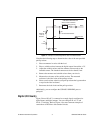
The default configuration of the USB-6501 OEM DIO ports is open-drain,
allowing 5 V operation, with an onboard 4.7 kΩ pull-up resistor. An
external, user-provided, pull-up resistor can be added to increase the source
current drive up to a 8.5 mA limit per line, as shown in Figure 4.
Table 2. Signal Descriptions
Signal Name Direction Description
P0.<0..7>
P1.<0..7>
P2.<0..6>
Input or
Output
Digital I/O Signals—You can individually configure
each signal as an input or output.
P2.7 (CTR 0 SRC) Input or
Output
This pin is configurable as either a digital line or an
event counter.
Digital I/O Signal—As a digital line, this signal can be
used as an input or output.
CTR—As a counter, this signal can be used as an event
counter input source.
+5 V Output +5 V—The voltage source provided by the USB host.
The voltage is nominally 5 V, but varies from system to
system.
GND — Ground—The reference for the digital signals and the
+5 VDC supply.


