


Motor Control I/O Board User’s Manual
For the instruction descriptions, refer to the 78K/0 Series Instruction User’s Manual (U12326E)
3. Hardware Setup
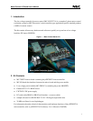
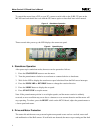
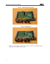
The kit can be purchased as one unit with all three boards connected as shown below:
Figure 2. MC-LV-KIT-714 Boards Stacked Up
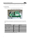
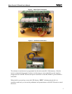
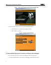
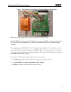
To attach the motor, connect the phase U, V and W terminals to the J3 connector block on the MC-
PWR-LV power board and the Hall sensor terminals to the J5 connector block on the MC-IO control
board.
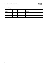
Table 1. Motor Connections
Pittman N2311 Motor Terminals MC-IO MV-PWR-LV
Phase U - Beige — J3 - 1
Phase V - Red — J3 - 2
Phase W - Orange — J3 - 3
Hall sensor 1 - Gray J5–13 —
Hall sensor 2 - Blue J5–14 —
Hall sensor 3 - White J5–7 —
Hall sensor 5VDC - Purple J5–6 —
Hall sensor GND - Black J5–5 —
Motor terminal connections are shown in Figures 3 and 4.
2