


Motor Control I/O Board User’s Manual
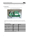
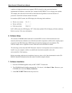
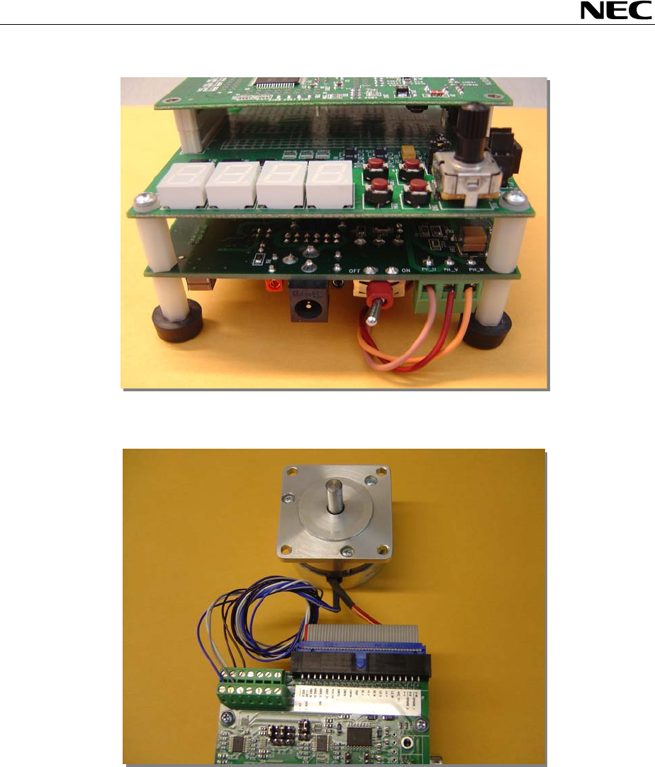
Figure 3. Motor Phase Connections
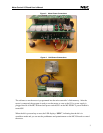
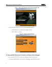
Figure 4. Hall Sensor Connections
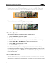
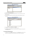
The software to run the motor is programmed into the microcontroller’s flash memory. After the
motor is connected, the program is ready to run the motor as soon as the 15V
DC power supply is
plugged into J6 of the MC-IO board and power switch SW1 on the MC-PWR-LV power module is
turned ON.
When the kit is powered up or reset, the LED displays “SELF”, indicating that the kit is in
standalone mode and you can use the pushbuttons and potentiometer on the MC-IO board to control
the motor.
3