


5. Make sure the appropriate BNC cable is used. Should the
graphics adapter require a connector other than the 15 pin
mini D-sub male included with the monitor, please call NEC
at (800) 820-1230. Connect cable to system.
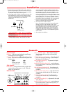
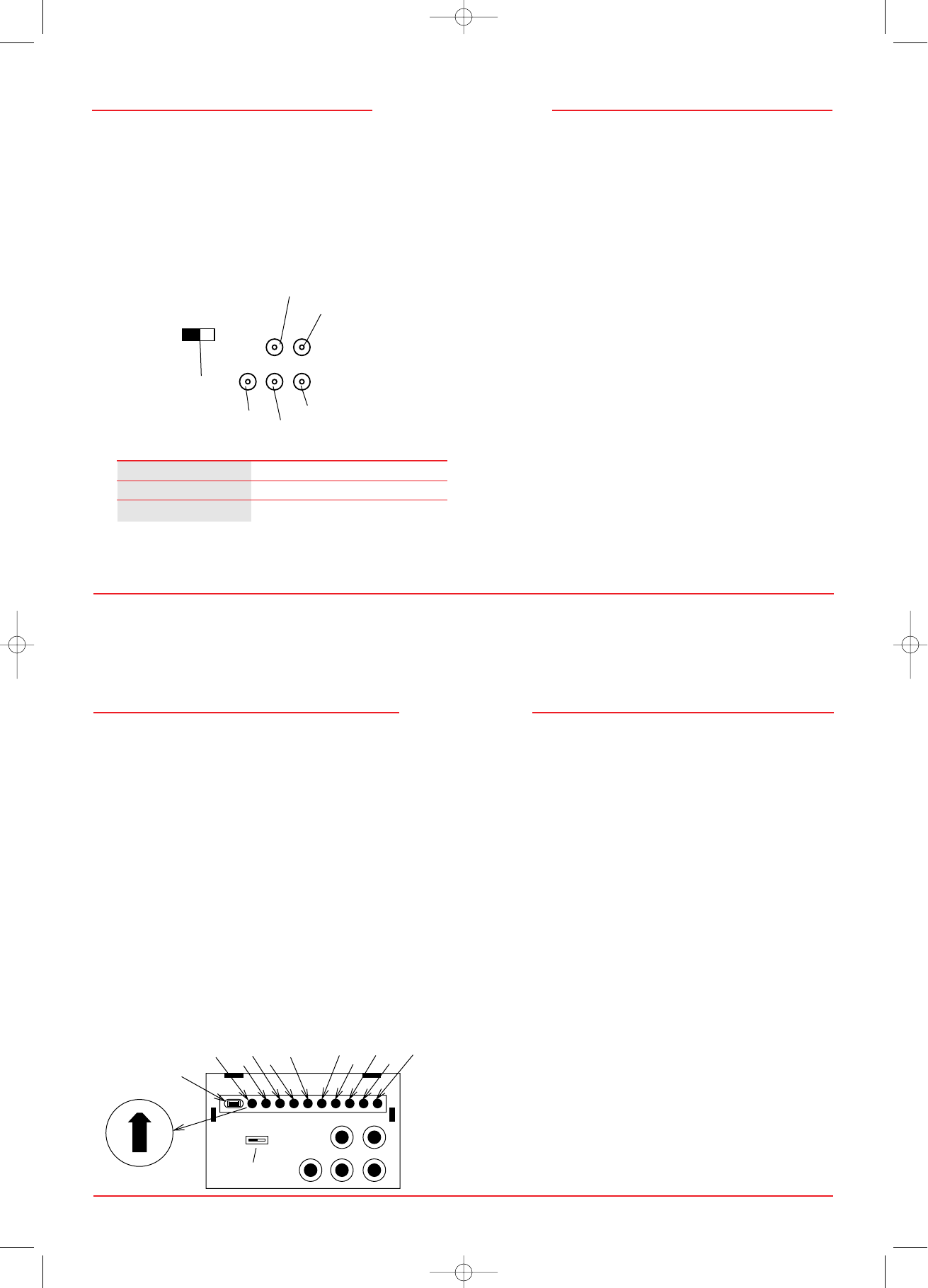
6. Connect BNC cables as follows according to the input video
mode selected above. (Note: incorrect cable connections
may result in irregular operation, damage display quality/
components of LCD module, and/or shorten the
module’s life.)
Input Video Mode H/CS VS R G/SYNC B
Separate Sync OOOOO
Composite Sync OXOOO
Sync on Green XXOOO
O - BNC connector is utilized; X - BNC connector is not utilized
Connect the red BNC cable to the BNC connector on the
monitor labeled R. The green BNC cable should be connec-
ted to the BNC connector on the monitor labeled G. The
blue BNC cable should be connected to the BNC connector
on the monitor labeled B. If you have a fourth BNC connec-
tor (Composite Sync), connect it to the BNC connector on the
monitor labeled H/CS. If you have a fifth BNC connector
(Vertical Sync), connect it to the BNC connector on the moni-
tor labeled VS. Please see Appendix 1 for pin assignments.
7. Connect one end of the power cable to the LCD1280
monitor and the other end to the power outlet.
8. Turn on the monitor and the computer.
Note: If the settings and connections were made properly,
the LED on the front of the LCD1280 will show green.
If the LED displays an amber color, the monitor is not receiv-
ing the appropriate input. Please make certain that the
above settings were made properly. If the LED continues
to display an amber color or the monitor is not displaying
a stable image, please refer to the Troubleshooting section
of this manual.
9. This completes the installation.
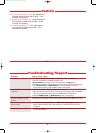
Front Controls:
Brightness: slide type control adjusts the overall image
and background screen brightness.
LED Power Indicator Light: indicates the monitor’s power
mode. Each mode reduces the amount of power used
by the monitor:
Mode Light
ON green
Stand By & Suspend amber
Power Switch, OFF no light
Side Control:
Power Switch: push type button located on right side of
monitor base turns the power on or off. When the
power is on, the LED is lit.
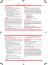
Rear Controls:
SYNC Mode Select Switch: allows selection between
Standard mode (OFF) and Sync on Green (ON)
priority mode.
H-SEL Pixel Frequency Select Switch: selects the external
pixel clock source for WS timing 1 (107.5 MHz) or
WS timing 2 (107.352 MHz).
WS Clock Delay Adjust (H-C): adjustment of WS pixel
clock delay rate.
Rough WS Horizontal Adjust (H-H1): rough adjustment
for horizontal position of WS mode (16 dot increment
per operation).
Fine WS Horizontal Adjust (H-H2): fine adjustment for
horizontal position of WS mode (1 dot increment per
operation).
Rough WS Vertical Adjust (H-V1): rough adjustment for
vertical position of WS mode (16 line increment per
operation).
Fine WS Vertical Adjust (H-V2): fine adjustment for
vertical position of WS mode (1 line increment per
operation).
VGA Clock Delay Adjust (V-C): adjustment of VGA pixel
clock delay rate.
Rough VGA Horizontal Adjust (V-H1): rough adjustment
for horizontal position of VGA mode (32 pixel / 16
dot increment per operation).
Controls
6
7
Installation
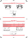
H Sync/Composite Sync
V Sync
Sync Mode Select
Green / Sync on Green
Red
Blue
G/SYNC B
H/CS
OFF ON
SYNC
VS
R
C
E
A
8
6
4
SYNC
OFF
Sync Mode Select
H-SEL
Pixel Frequency
Select
H/CS VS
G/SYNCRB
H-C
H-H1
H-H2
H-V1
V-C
V-H1
V-H2
V-V1
V-V2
H-V2
ON
2
0
Display Position / Clock Delay Adjust
LCD1280 10/29/99 9:25 AM Page 6