


7
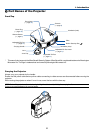
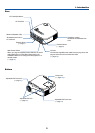
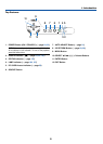
1. Introduction
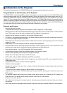
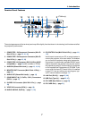
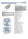
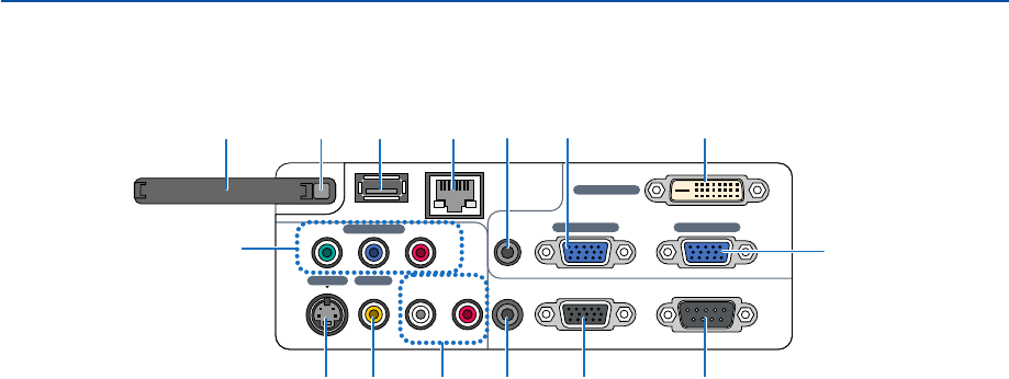
Ter minal Panel Features
PC CARD
COMPONENT IN
USB LAN
AUDIO IN
COMPUTER 3 IN
COMPUTER 1 IN COMPUTER 2 IN
PC CONTROL
MONITOR OUT
AUDIO OUT
S-VIDEO IN VIDEO IN
AUDIO IN
Cb/Pb
L/MONO R
Y
Cr/Pr
14
3
2
11
569 108
7
1
4
13 1215
1. COMPUTER 1 IN/Component Connector (Mini D-
Sub 15 Pin) (→ page 13, 15, 16)
2. COMPUTER 2 IN/Component Connector (Mini D-
Sub 15 Pin) (→ page 13, 16)
3. COMPUTER 3 IN Connector (DVI-D 24 Pin) (HDCP
compatible) (→ page 14) (Not available on LT280)
4. AUDIO IN (Stereo Mini Jack) (→ page 13, 14, 16)
5. MONITOR OUT Connector (Mini D-Sub 15 Pin) (→
page 16)
6. AUDIO OUT (Stereo Mini Jack) (→ page 16)
7. COMPONENT IN (Y, Cb/Pb, Cr/Pr) Connectors
(RCA) (→ page 17)
8. S-VIDEO IN Connector (Mini DIN 4 Pin) (→ page
18)
9. VIDEO IN Connector (RCA) (→ page 18)
10. AUDIO L/MONO, R (RCA) (→ page 17, 18)
11. PC CONTROL Port (Mini D-Sub 9 Pin) (→ page 116,
117)
Use this port to connect your PC or control system to
control your projector via a serial cable. This enables
you to control the projector using serial communica-
tion protocol. A commercially available RS232C cross
cable is required to use this port. You can also control
the projector by using PC Control Utility 3.0 contained
on the supplied User Supportware 3 CD-ROM. To do
so you must first have PC Control Utility 3.0 installed
on your PC. If you are writing your own program, typi-
cal PC control codes are on page 116.
12. LAN Port (RJ-45) (→ page 19, 48)
13. USB Port (Type A) (→ page 35, 47)
14. PC CARD Eject Button (→ page 22)
15. PC CARD Slot (→ page 21)
(LT380 only)
The actual appearance of the terminal panel may differ slightly from that shown in the drawing, but this does not affect
the projector's performance.