


(English)
28
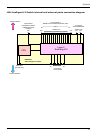
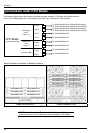
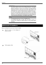
Connection with CPU Blade
The following figure shows the network connection diagram between CPU Blades and Switch Modules.
Port 3 and 4 of Mezzanine slot 2 are available only when Type II Mezzanine Card installed.
CPU Blade
(Express5800/120Bb-6)
on-board LAN
Mezzanine
slot1
(Type-1)
Mezzanine
slot 2
(Type-1,2)
Port2
Port1
Port2
Port1
Port2
Port1
To Switch Module slot 6
To Switch Module slot 5
To Switch Module slot 4
To Switch Module slot 3
To Switch Module slot 2
To Switch Module slot 1
To Switch Module slot 6 in Blade Enclosure(6U)
To Switch Module slot 8 in Blade Enclosure(10U)
Port4
Port3
To Switch Module slot 5 in Blade Enclosure(6U)
To Switch Module slot 7 in Blade Enclosure(10U)
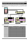
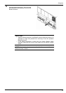
Switch Module slot number in Blade Enclosure
Switch Module slot 6
Switch Module slot 5
Switch Module slot 4Switch Module slot 3
Switch Module slot 2
Switch Module slot 1
Switch Module slot 1
Switch Module slot 3
Switch Module slot 5
Switch Module slot 7
Switch Module slot 2
Switch Module slot 4
Switch Module slot 6
Switch Module slot 8
Blade Enclosure (6U) Blade Enclosure (10U)
Rear View
NOTE: Switch Module slots 7 and 8 of Blade Enclosure (10U) are
available only when Type II Mezzanine Card is installed in CPU Blade.