


(English)
29
port
20
Uplink ports
Serial Port
port
1
port
16
port
17
port
19
N8406-022
1Gb Intelligent L2 Switch
10/100/1000Mbps
10/100Mbps
1000Mbps fixed
1000Mbpsfixed
CPU
Layer 2
Switching LSI
port
18
port
24
N8406-013
1Gb Interlink Expansion Card
CPU Blade
port
20
Uplink ports
Serial Port
port
1
port
16
port
17
port
19
N8406-022
1Gb Intelligent L2 Switch
10/100/1000Mbps
10/100Mbps
1000Mbpsfixed
1000Mbps fixed
CPU
Layer 2
Switching LSI
port
18
port
24
Mezzanine
slot 1
on-board LAN
To port 1 To port 9 To port 1 To port 9
Switch Module slot 1 Switch Module slot 2
Switch Module slot 3,4
Blade Slot 1
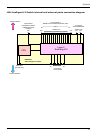
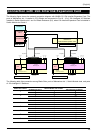
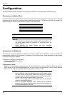
Connection with 1Gb Interlink Expansion Card
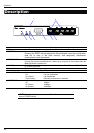
The following figure shows the network connection diagram with N8406-013 1Gb Interlink Expansion Card. The
ports of Mezzanine slot 1 installed in CPU Blades are connected to Port 9 - 16 of 1Gb Intelligent L2 Switches
installed in Switch Module slot 1 and 2 of Blade Enclosure (6U), when 1Gb Interlink Expansion Card is installed in
Switch Module slot 3 and 4.
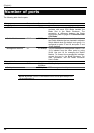
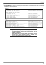
The following table lists connection among Blade Slots, ports of Mezzanine slot 1, Switch Module slots, and ports
of 1Gb Intelligent L2 Switches.
Blade Slot number
Port number
of Mezzanine slot 1
Switch Module slot number
Port number of
1Gb Intelligent L2 Switch
1 1 9 1
2 2 9
1 1 10 2
2 2 10
1 1 11 3
2 2 11
1 1 12 4
2 2 12
1 1 13 5
2 2 13
1 1 14 6
2 2 14
1 1 15 7
2 2 15
1 1 16 8
2 2 16