


7
1. Introduction
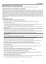
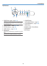
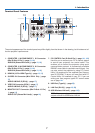
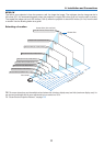
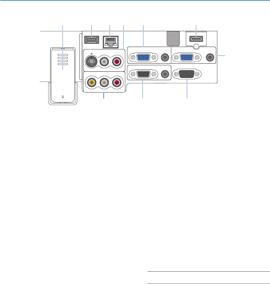
Terminal Panel Features
1. COMPUTER 1 IN/COMPONENT 1 IN Connector
(Mini D-Sub 15 Pin) (
→
page 12, 16)
AUDIO IN (Stereo Mini Jack) (
→
page 12, 16)
2. COMPUTER 2 IN/COMPONENT 2 IN Connector
(Mini D-Sub 15 Pin) (
→
page 12, 16)
AUDIO IN (Stereo Mini Jack) (
→
page 12, 16)
3. HDMI IN (19 Pin HDMI Type A) (
→
page 13, 15)
4. S-VIDEO IN Connector (Mini DIN 4 Pin) (
→
page
17)
AUDIO L/MONO, R (RCA) (
→
page 17)
5. VIDEO IN Connector (RCA) (
→
page 17)
AUDIO L/MONO, R (RCA) (
→
page 17)
6. MONITOR OUT Connector (Mini D-Sub 15 Pin)
(
→
page 14)
AUDIO OUT (Stereo Mini Jack) (
→
page 14)
7.
PC CONTROL Port (D-Sub 9 Pin) (
→
page 141, 142)
Use this port to connect your PC or control system
to control your projector via a serial cable. This
enables you to control the projector using serial
communication protocol. A commercially available
RS232C cross cable is required to use this port. You
can also control the projector by using PC Control
Utility 3.0 contained on the supplied User Support-
ware 5 CD-ROM. To do so you must first have PC
Control Utility 3.0 installed on your PC. If you are
writing your own program, typical PC control codes
are on page 141.
8. USB Port (Type A) (
→
page 35)
9. LAN Port (RJ-45) (
→
page 18, 99)
10. USB Wireless LAN unit (
→
page 143)
NOTE: A dummy cover is provided on this location of the
projector without the USB Wireless LAN Unit.
The actual appearance of the terminal panel may differ slightly from that shown in the drawing, but this does not af-
fect the projector’s performance.
WIRELESS
WIRELESS
USB
(
LAN
)
VIDEO IN
AUDIO IN
USB
LAN
AUDIO IN
HDMI IN
AUDIO IN
COMPUTER /
COMPONENT 2 IN
COMPUTER /
COMPONENT 1 IN
PC CONTROL
MONITOR OUT
AUDIO OUT
S-VIDEO IN
AUDIO IN
L/MONO
L/MONO
R
R
2
6 75
110 4
38 9