


GS700TS Hardware Installation Guide
Installation 2-32
v1.0, November 2007
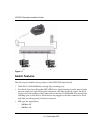
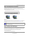
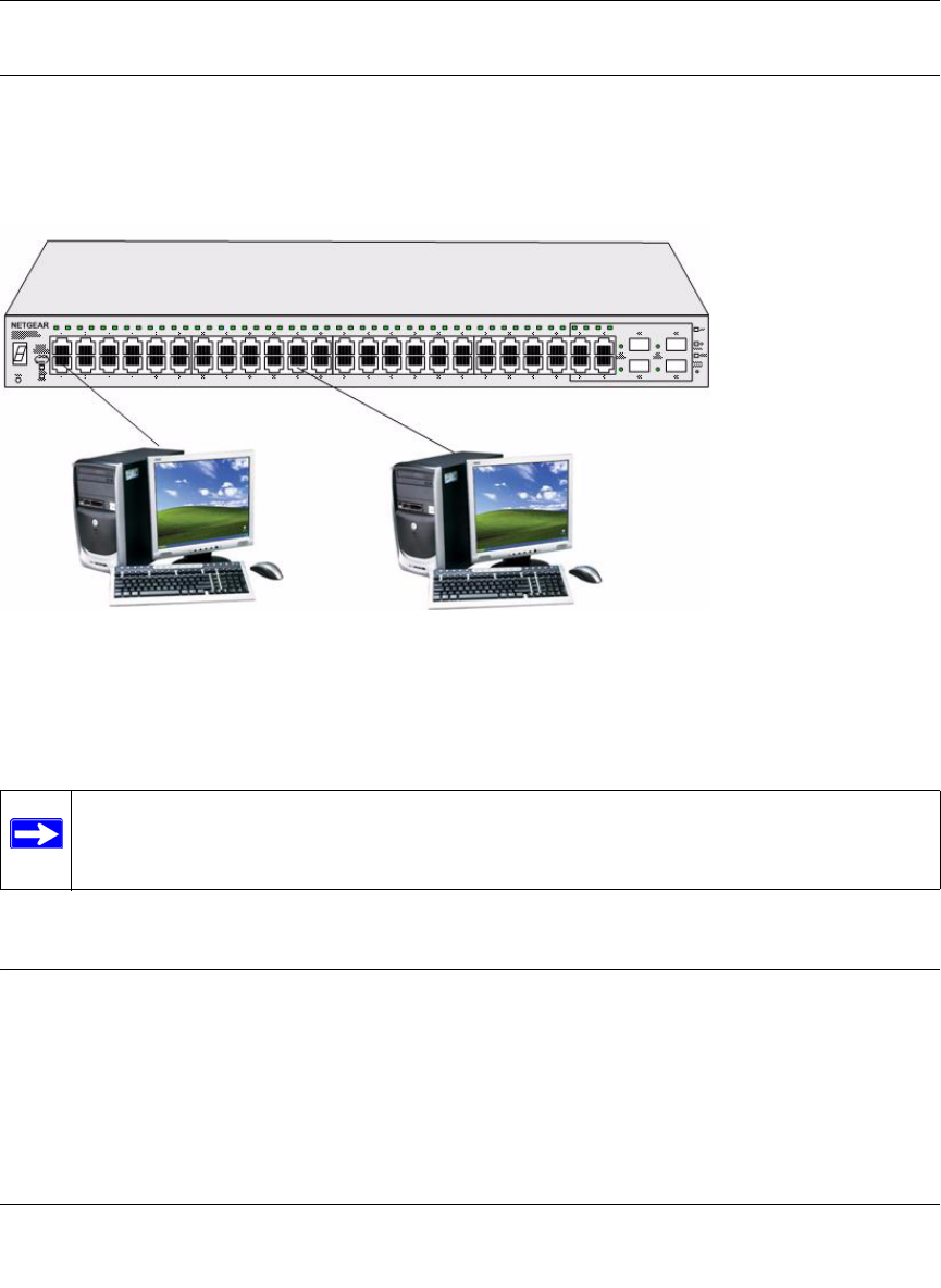
Step 4: Connecting Devices to the Switch
The following procedure describes how to connect PCs to the switch’s RJ-45 ports. The
NETGEAR Smart Switch contains Auto Uplink™ technology, which allows you to attach devices
using either straight-through or crossover cables.
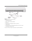
Connect each PC to an RJ-45 network port on the Switch front panel (Figure 2-2). Use Category 5
(Cat5) Unshielded Twisted-Pair (UTP) cable terminated with an RJ-45 connector for these
connections.
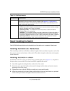
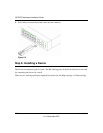
Step 5: Installing an SFP GBIC Module
The following procedure describes how to install an SFP Gigabit Ethernet module in the switch’s
Gigabit module bay. Standard SFP GBIC modules are sold separately from the Smart Switch. If
you do not plan to install an SFP GBIC module at this time, skip this procedure.
To install an SFP GBIC module:
1. Insert the SFP module into the SFP module bay.
Figure 2-2
Note: Ethernet specifications limit the cable length between the switch and the attached
device to 100 m (328 ft.).