


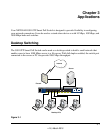


GS110TP Hardware Installation Guide
Installation 4-3
v1.0, March 2010
Step 3: Checking the Installation
Before applying power to the switch, perform the following:
• Inspect the equipment thoroughly.
• Verify that all cables are installed correctly.
• Check cable routing to make sure cables are not damaged or creating a safety hazard.
• Ensure all equipment is mounted properly and securely.
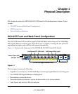
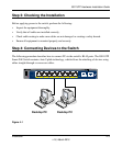
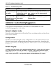
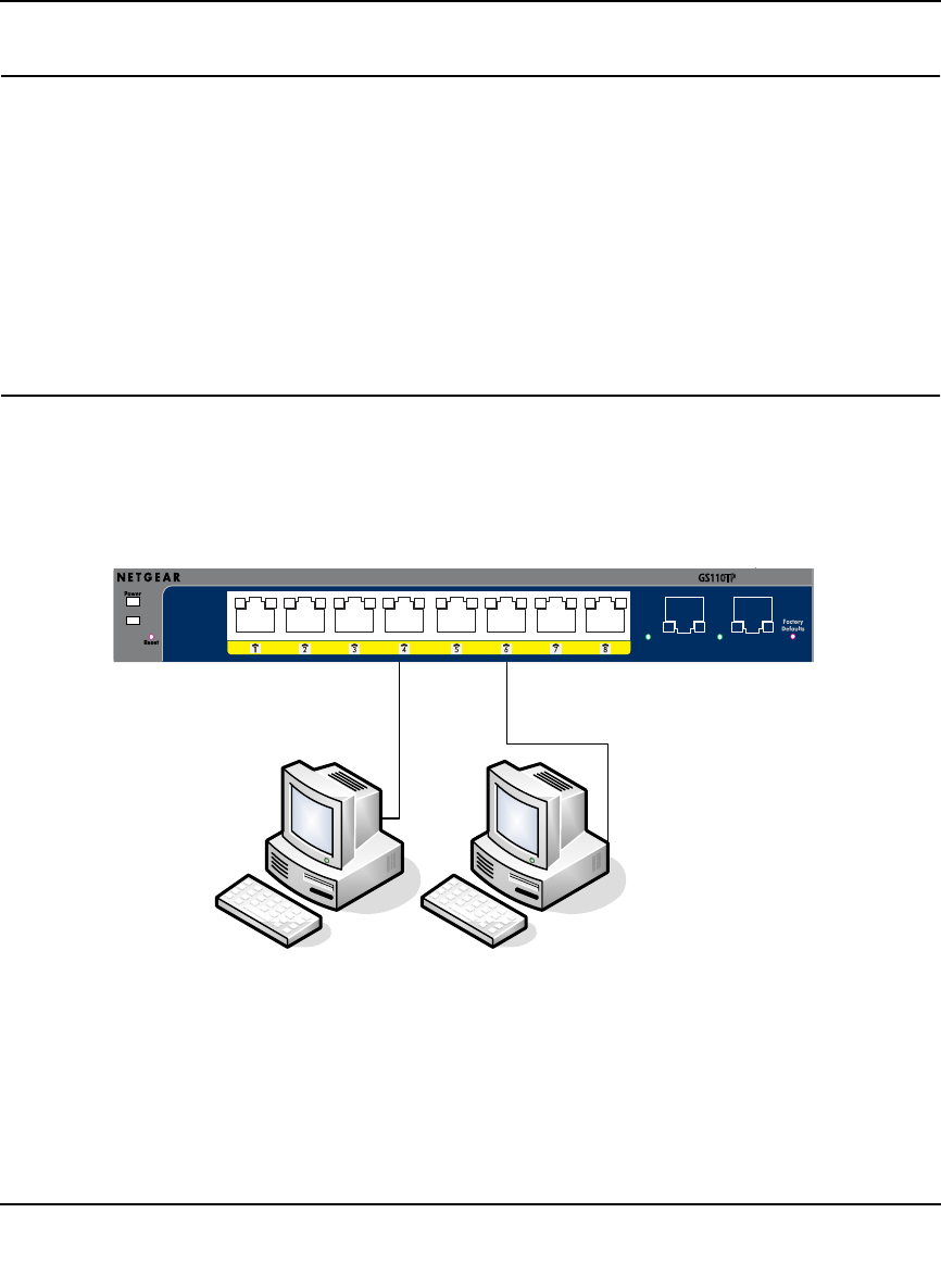
Step 4: Connecting Devices to the Switch
The following procedure describes how to connect PCs to the switch’s RJ-45 ports. The GS110TP
Smart PoE Switch contains Auto Uplink technology, which allows the attaching of devices using
either straight-through or crossover cables.
Desktop PC
`
Desktop PC
`
P
RO
S
AFE
GS110TP
Link/Act
Link/Act Mode
Green
=
Link at 1000M
Yellow
=
Link at 100M/10M
Blink
=
ACT
PoE Mode
Green
=
PoE Powered
Yellow
=
PoE Fault
Link/Act PoE
PoE
Ports
Link/Act
9F 10F
PoE Max
Figure 4-1