Page 11 of 24
LED Descriptions
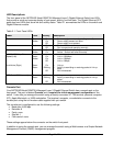
The front panel of the NETGEAR Model GSM7324 Managed Layer 3 Gigabit Ethernet Switch has LEDs
that provide a quick and accurate display of port speed, activity, and link state. The Gigabit Ethernet SFP
ports also have LEDs that show link and activity status. Table 2-1 summarizes the LEDs on the switch and
Gigabit Ethernet module.
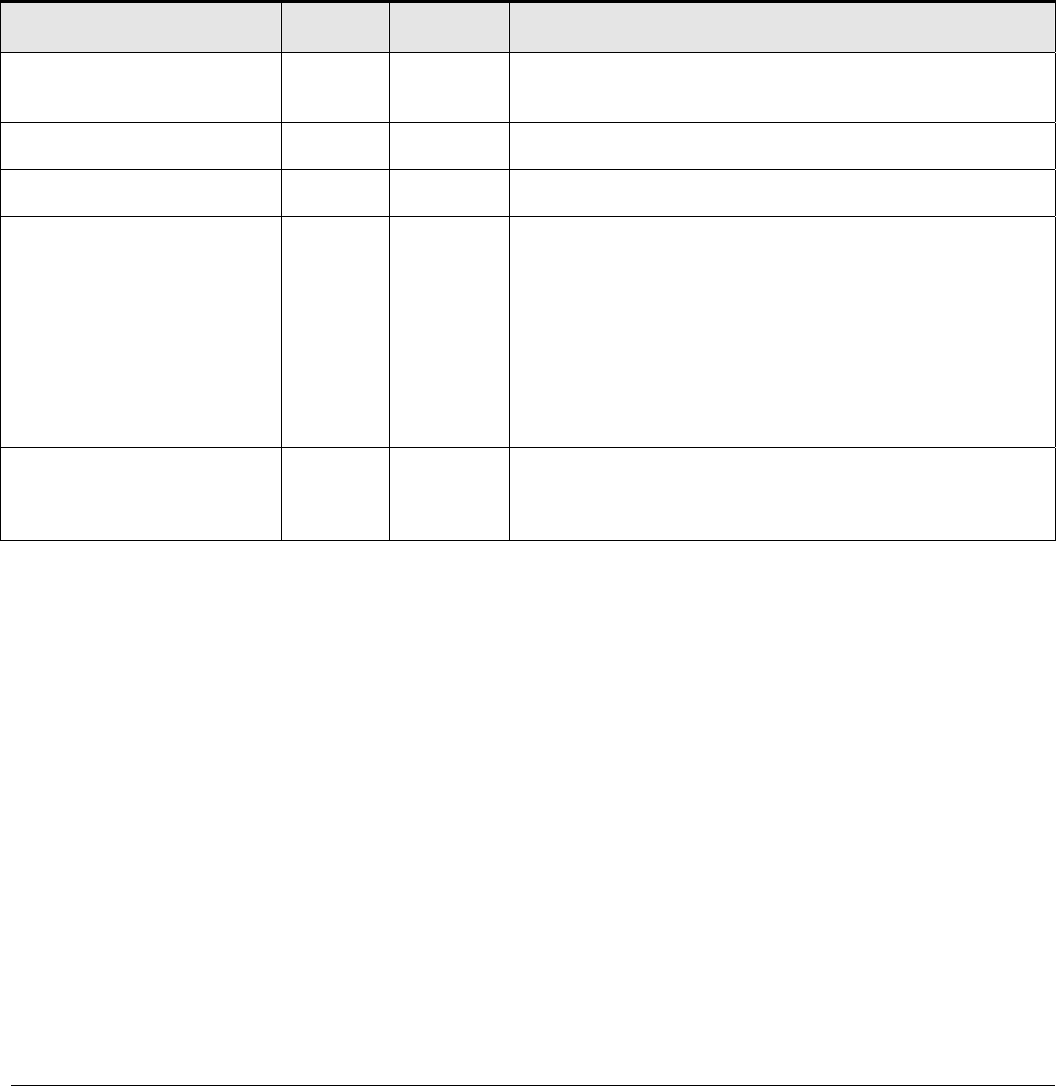
Table 2-1. Front Panel LEDs:
Label Color Activity Description
Power Green
Amber
On
On
Off
Power supply present and operating normally
Power supply present but failed
Power supply is not present
Fan
Red
On
Off
Fan has failed
Fan is present and operating normally
Status
Green
Amber
On
On
Green – Switch is operating normally
Amber – Switch has failed to bootup
10/100/1000M bps Port
Speed (Left)
Link/Active (Right)
Green
Amber
Green
Green
On
On
Off
On
Blinking
Off
Link in 1000Mbps
Link in 100Mbps
Link in 10Mbps
Link up
Activity, transmitting or receiving packet in link up
state
No Link detected
SFP Port (1000M bps only) Green
Green
On
Blinking
Off
Link up
Activity, transmitting or receiving packet in link up
status
No Link detected
Console Port
Your NETGEAR Model GSM7324 Managed Layer 3 Gigabit Ethernet Switch has a console port on the
front panel. This port is labeled Console and is required for initial management configuration of the
switch. It also lets you manage the switch using a directly connected VT-100 terminal, personal computer
(PC), Apple Macintosh, or UNIX workstation. The terminal, computer, or workstation connects to the
console port using the null-modem cable supplied with your switch.
The console port is configured to use the following settings:
• Baud rate: 9,600 bps
• Data bits: 8
• Parity: none
• Stop bit: 1
• Flow control: none
These settings appear below the connector on the switch front panel.
In addition to using the console port, you can manage the switch using a Web browser or a Simple Network
Management Protocol (SNMP) management program.


