


4
WAN Probe Kit Quick Installation Diagrams
WAN Probe Kit Quick Installation Diagrams
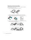
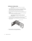
Follow the diagrammed steps below to install the WAN Probe Kit. More detailed NIC and
software installation instructions follow in this Guide.
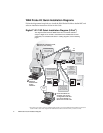
Digital T1/E1 TAP Quick Installation Diagram (2-Port
1
)
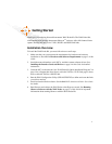
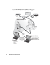
The diagram below shows the WAN Probe Kit as it would be cabled to
analyze a digital T1/E1 link with a Channel Service Unit/Data Service Unit
(CSU/DSU). For a DS3/E3 and Serial T1 cabling diagrams, see the following
pages.
1. The 4-Port version of this system has an additional PC interface card, and an additional TAP and cable kit. Connect the
second TAP kit as shown in the diagram. Run NIWANCFG to define and name the links you want to monitor.
TX
MONITOR
LINK 1 LINK 2
IN
OUT
RX
MONITOR
IN
OUT
RX
MONITOR
TX
MONITOR
TX
RX
TX
RX
CSU/DSU
(DTE)
T1
TAP
10/100
NIC
A
T1 Line
(DCE)
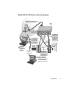
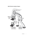
Move the DCE
connector from
the T1 line to
one of the
ports on the TAP.
IN
Use the
supplied T1
cable to
complete the
passthrough
Link back to the
T1 Line.
Probe
Service
Installed
Observer
Console
TCP/IP
LAN
Use the supplied
10/100 cable to
connect the Probe
to a TCP/IP LAN
with an Observer
system attached.
Connect Interface
card to TAP with
Interface cable.
TAP sockets
and cable
are
provided for
analyzing a
2nd load-
balanced
line, if
necessary.
2
Install the
Network
Instruments
Probe
software.
3
From the Observer
Console, the newly-
configured Probe will
now be available on
Observer’s Probe List.
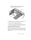
1
Install the interface cards,
drivers, and cabling.
WAN
Card