


Installing the Interface Cards and Drivers
25
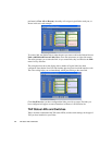
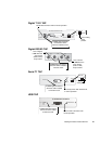
Digital T1/E1 TAP
Digital DS3/E3 TAP
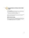
Serial T1 TAP
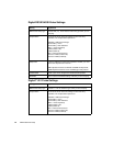
HSSI TAP
TEST
LOOP
POWER
TO PROBE
NETWORK INTERFACE UNIT
INTERFACE SELECTOR
E1
T1
RJ
BANTAM
E1
T1
RJ
BANTAM
LOOP Should remain unlit for normal operation.
Leave setting
on RJ
position.
POWER light should be
lit whenever TAP is
cabled to Interface Card.
DTE
POWER
DCE
LOS
LOF
LOS
LOF
DSE
IN
OUT
IN
OUT
Loss of Signal,
—unlit when the
given device
(DTE or DCE)
drops carrier.
Loss of Frame
—unlit when the
given device
(DTE or DCE)
drops a frame.
POWER light should be lit
whenever TAP is cabled to
Interface Card.
B
POWER
DTE
DCE
MODE
AB
ACTIVE OUTPUT
Link activity LEDs--both should be lit
for normal operation.
MODE
AB
Leave on
setting B.
POWER light should be lit
whenever TAP is cabled
to Interface Card.
B
POWER
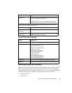
T3 WAN MONITOR TAP MODULE
INTERLOCK
OUTPUT TO PROBE
Interlock LED--should be lit for
normal o
p
eration.
POWER light should be lit
whenever TAP is cabled
to Interface Card.