


ASI-IP-GTW User's Manual
Page 13
Note: Some units are delivered to use 48 VDC power. These units have
a 3-pin power D-SUB connector instead of the mains connector.
7. LEDs. The ASI-IP-GTW provides on the rear four LEDs related to the
operation of the equipment. In addition, there are LEDs related to the
ASI ports, the management port and the data port.
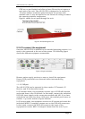
1.5.4 Construction
The ASI to IP Gateway consists of a main board and one or two ASI
boards mounted horizontally in a screened, self-ventilated cabinet. The
unit is 1RU high and two units can be mounted side-by-side in a 19
inch rack. All inputs and outputs are available at rear panel and there
are no front panel keypads or display.
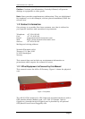
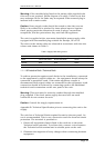
Figure 3 shows the rear panel of
the unit.
Figure 3. Rear view
1.5.5 Hardware Options
1.1.1.5 4 additional ASI ports
The ASI-IP-GTW is at least fitted with 4 ASI ports from factory. 1 to 4 of
these inputs are enabled from factory. As an option, the unit can be
fitted with an additional ASI module, providing 4 additional ASI ports,
which gives a total of 8 ASI ports.
1.1.1.6 SFP Module
As a factory option, the ASI-IP-GTW can be equipped with an SFP slot
to feature optical Gigabit or a second, redundant electrical Gigabit port.
The SFP module itself is not provided.
1.1.1.7 GPS Module
As a factory option, the ASI-IP-GTW can be equipped with a sync signal
input module. This module gives the ASI-IP-GTW the option to sync to
either a 1pps or 10MHz signal.
1.1.1.8 SFP/GPS Module
As a factory option, the ASI-IP-GTW can be equipped with an SFP slot
to feature optical Gigabit or a second, redundant electrical Gigabit port.
The SFP module itself is not provided. This module also includes a
1pps input for use as a sync signal.