


NTI UNIMUX SERIES USB KVM SWITCH
7
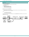
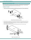
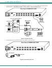
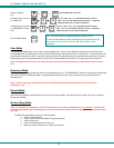
5. Connect each CPU to the USB switch using a USB-DHEXT-xx-MM (xx=3, 6, 10, or 15 foot) cable for each video and input
device connection – REQUIRED (not supplied). (See Fig. 5 below.) Cables are available from NTI.
Figure 5- Connect each CPU
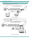
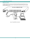
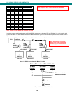
7. Connect the AC power cord with IEC connector to the UNIMUX. (See Fig. 6 below.)
Figure 6- Connect the power cord
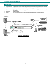
USB Type A Female
USB Type A Male
DVI Female
Video Connector
Rear View of Windows USB CPU
Video Port
Input Device Port
HDMI Type A
Video Connector
Mating Face of
DVI Male
Mating Face of
HDMI Type A Male
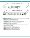
Rear View of UNIMUX-DVI-16HD
CPU 1CPU 2CPU 3CPU 4CPU 5CPU 6CPU 7CPU 8
CPU 9CPU 10CPU 11CPU 12CPU 13CPU 14CPU 15CPU 16
RS232
250V,2A
MONITOR
NTI
Tel:330-562-7070
Fax:330-562-1999
1275 Danner Dr
Aurora, OH 44202
www.networktechinc.com
R
USB-DHEXT-xx-MM
(3,6,10 and 15 foot cables available)
Rear View of UNIMUX-DVI-16HD
CPU 1CPU 2CPU 3CPU 4CPU 5CPU 6CPU 7CPU 8
CPU 9CPU 10CPU 11CPU 12CPU 13CPU 14CPU 15CPU 16
RS232
250V,2A
MONITOR
NTI
Tel:330-562-7070
Fax:330-562-1999
1275 Danner Dr
Aurora, OH 44202
www.networktechinc.com
R
Power cord
IEC Connector