


NTI UNIMUX SERIES USB KVM SWITCH
6
INSTALLATION
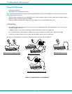
1. It is not necessary to turn the CPUs or monitors OFF during this installation.
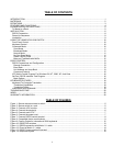
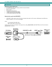
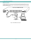
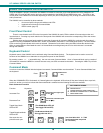
2. Connect a DVI-to-DVI cable (should have come with the monitor) from a DVI monitor to the “MONTOR” connector on the
rear of the UNIMUX (See Fig. 3 below.)
Figure 3- Connect a DVI monitor
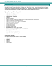
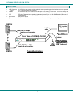
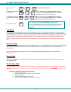
3. Connect the male USB type A connector on the keyboard cable to either one of the two USB type A female connectors
labeled with the USB symbol ( ) on the rear of the UNIMUX.
4. Connect the male USB type A connector on the mouse cable to the remaining USB type A female connector labeled with the
USB symbol on the rear of the UNIMUX.
Figure 4- Connect the device(s)
DVI Enabled
Monitor
Mating Face of
DVI Male
Rear View of UNIMUX-DVI-16HD
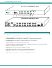
CPU 1CPU 2CPU 3CPU 4CPU 5CPU 6CPU 7CPU 8
CPU 9CPU 10CPU 11CPU 12CPU 13CPU 14CPU 15CPU 16
RS232
250V,2A
MONITOR
NTI
Tel:330-562-7070
Fax:330-562-1999
1275 Danner Dr
Aurora, OH 44202
www.n etworktech inc.com
R
DVI-D-Male
Existing Cable
USB Keyboard
USB
Mouse
USB Type A
Male Connectors
USB Type A Male
USB Type A Female
Rear View of UNIMUX-DVI-16HD
CPU 1CPU 2CPU 3CPU 4CPU 5CPU 6CPU 7CPU 8
CPU 9CPU 10CPU 11CPU 12CPU 13CPU 14CPU 15CPU 16
RS232
250V,2A
MONITOR
NTI
Tel:330-562-7070
Fax:330-562-1999
1275 Danner Dr
Aurora, OH 44202
www.networktechinc.com
R