


Installation
2 - 1
2 - Installation
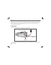
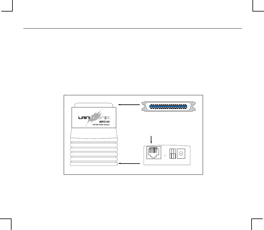
2.1 Product Description
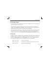
The front panel of the MPS has a Test button, LEDs, a power connector, and one of the
following Ethernet ports: a BNC connector for 10BASE-2 (MPS1-2), an RJ45 port for
10BASE-T (MPS1-T), or an RJ45 port for 10/100BASE-T (MPS100). The rear panel has a
Centronics connector.
The
LINK
LED is solid green when there is a valid Ethernet network connection. The
ACT
(Activity) LED ßashes green or red when the server is in use. The
100
(100 MBit)
LED (MPS100 only) is solid green when a 100BASE-T network is connected.
MPS100
TEST
LINK
5VDC
AC
T
100
Centronics Connector
10/100BASE-T Port
“front”
“back”