


INSTALLATION (CONTINUED)
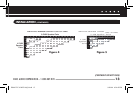
6. Set the Impedance Magnification Switch (See Figure 7) as determined by the IM charts (Figures 4 and 5).
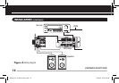
7. Plug the connectors into the volume control as shown in
Figure 6. The inputs of the IM volume control are the
connector pins labeled AMPLIFIER. The outputs are the connector pins labeled SPEAKERS.
NOTE: IF YOU REVERSE THESE CONNECTIONS, THE VOLUME CONTROL WON’T
FUNCTION PROPERLY.
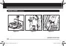
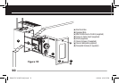
8. Connect the 2 conductor power-supply wiring between the volume control
(See Figure 8) and the receiver’s switched outlet or a Niles MVC HUB4
speaker/ power hub (See Figure 3).
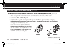
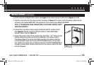
9. Secure the volume control to the junction box. Insert the 1-1/4
" device screws
into the oblong screw holes on the top and bottom of the volume control.
The oblong shape of the screw holes helps you place the volume control in
a vertical position. Align the screws with the threaded holes in the junction
box. Tighten the screws using a Phillips screwdriver. DO NOT OVERTIGHTEN. If
necessary, loosen these screws several turns so the volume control fits flush
with the faceplate.
Figure 9. Loosening the screws
for a Flush fit
NILES AUDIO CORPORATION – 1-800-BUY-HIFI
15
DS00317C-0 MVC100_R.indd 17 9/20/06 4:28:49 PM