6
S
IMPLIFIED
I
NFRARED
R
OUTER
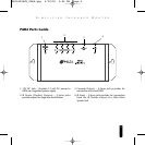
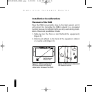
Installation Considerations (continued)
Before you begin, make sure that the flasher cables and the 12VDC power supply cable will
all reach the proposed location of the PAR4. Mark the cables with labels describing where
the cable originates (i.e. TV1) rather than which terminal on the PAR4 it should connect.
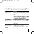
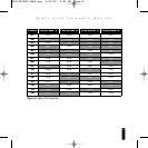
STEP DESCRIPTION
1. Connect and test the
power supply.
A) Plug the supplied 12VDC power supply into an unswitched
100-240V AC outlet.
B) Plug the connector into the socket labeled “power” on the
PAR4.
C) If the power LED on the PAR4 does not light, test the
unswitched AC outlet with another appliance. If the outlet tests
OK, you have a defective power supply which must be replaced
before you continue. If the red power LED illuminates unplug
the connector from the power socket and proceed.
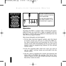
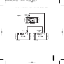
2. Plug the flashers (not sup-
plied) into the flasher outputs.
See figur
e 4.
A) Recommended flashers are Niles MF1 or MF1VF MicroFlashers.
If you need to extend the wire, use 2 conductor, 16 gauge
stranded wir
e.
B) When extending the flasher wire be sure to observe proper polarity.
C) The wire marked with the grey stripe is positive (+); the unmarked
lead is negative (-).
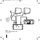
3. Connect the PAR4 to the
IR main system unit using
a 3.5mm mono cable of
appropriate length.
See figure 1.
A) Plug one end of the cable into the IR output of the main system
unit (a flasher output on any Niles MSU).
B) The other end of the cable is plugged into the jack labeled “IR
Input” on the PAR4.
C) During normal operation the blue IR indication LED will flicker
when the PAR4 is receiving IR data from the output device.
DS00429ACN_PAR4.qxp 3/30/05 3:06 PM Page 6