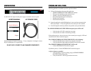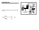
1. The external power supply is mounted on the rear panel of the
GEMINI EXPRESS MULTIPLEXER. The AC power cord must be
firmly inserted into the external power supply and strained relieved.
2. Insert the male end of the AC power cord into a properly wired
receptacle. All data & mode LED’s on the GEMINI EXPRESS
MULTIPLEXER will activate for two seconds and fade off. The
amber power LED on the front panel, the green power LED on the
top of the external power supply, and the “TX & RX” LEDs will
activate and remain on. If any terminals are on, the data activity
LEDs will activate. If express devices and an express host, are
attached, the port status LEDs (upper green LEDs) will activate.
Devices in a ring application will not show a sign on screen until the
ring is complete.
ACTIVE PAIR SETUPACTIVE PAIR SETUP
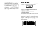
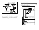
All GEMINI EXPRESS MULTIPLEXERS can be factory configured per
customer request. The factory default setting is Pins 4 & 5. Different
configurations will be indicated on the label on the bottom of the unit.
IDENTIFICATION LABEL
The active pair may be re-configured by performing the following procedure:
• Disconnect all power to the unit.
• Remove the two top cover screws located on the rear panel.
• Gently slide the top cover back one inch.
• Hold the top cover and tilt it up.
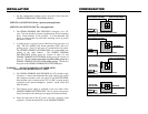
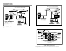
Reconfigure the jumpers located behind the RJ45 connectors as required. Settings
for polarity and active pair assignment are shown below:
ACTIVE PAIR JUMPER SETTINGS
It should be noted that connections to the DB25 and the RJ45s are mutually
exclusive. If any of the three pairs of the RJ45 are selected, the DB25 is
disconnected. If the DB25 is selected, the RJ45s are disconnected. All jumper
settings must be identical. To reinstall the top cover, tilt the top cover down, and
slide the top cover forward until it mates completely with the bottom cover.
Install the 2 top cover screws.
MODEL GXM8-45
PINS 4/5 3/6 1/2
S/N xxxxxxxxxx
RJ45 RJ45 RJ45
RJ45 (4/5) RJ45 (3/6) RJ45 (1/2)
RJ45
DB25


