


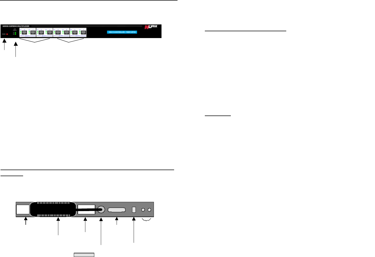
DESCRIPTIONDESCRIPTION
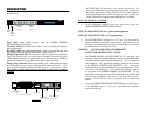
The GEMINI EXPRESS MULTIPLEXER’s indicators and connections are
described below.
Power LED Amber LED activates when the GEMINI EXPRESS
MULTIPLEXER is powered up.
TX Activity LED Green LED activates when a signal is transmitted to the fiber
optic aggregate link.
RX Activity LED Green LED activates when a signal is received from the fiber
optic aggregate link and the MULTIPLEXER synchronizes to it.
Polling Group Status LEDs The upper green LEDs are express mode indicators.
These LEDs activate when an express signal is detected and remain on until a
1MBPS signal is detected or a system reset occurs. The lower green LEDs are
data activity indicators. These LEDs activate when a signal is present.
Polling Group Connectors There are two polling groups. Each polling group has
been divided into two port groups. Polling group #1 consists of ports 0 - 3 (port
groups A & B) and Polling group #2 consists of ports 4 - 7 (port groups C & D).
Ports within a polling group must be connected to ports from a common
controller.
MULTIPLEXER will activate for two seconds and fade off. The
amber power LED on the front panel, the green power led on the top of
the external power supply, and the TX LED will activate and remain on.
At this time the data activity LEDs will flash at the host’s polling rate.
The RX LED will be off until the remote Multiplexer is installed.
Device side Multiplexer installation.
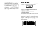
1) Set the configuration switches on the rear panel of the device side
GEMINI EXPRESS MULTIPLEXER as follows:
SWITCH 1 OFFSWITCH 2 ON for a point to point application
or
SWITCH 1 OFFSWITCH 2 OFF for a ring application.
2) The MULTIPLEXER is designed for a 19” rack. The unit should be
properly installed using all four mounting holes. Rack hardware is not
provided. It is recommended that plastic or nylon washers be used under
mounting screws to protect the star’s finish.
WARNING DO NOT LOOK INTO ANY FIBER OPTIC
CONNECTOR OR FIBER OPTIC CABLE!
3. The GEMINI EXPRESS MULTIPLEXER has ST style fiber optic
connectors. For point to point applications, connect the multimode fiber
optic cable attached to the host side Multiplexer ’s ”TX” to the device
side multiplexer ’s ”RX” optical link connector located on the rear panel
of the GEMINI EXPRESS MULTIPLEXER , and connect the
multimode fiber optic cable attached to the host side Multiplexer ’s ”RX”
to the device side Multiplexer ’s ”TX” optical link connector located on
the rear panel of the GEMINI EXPRESS MULTIPLEXER. For ring
applications, connect the fiber optic TX of a Multiplexer to the fiber optic
RX of the next multiplexer down stream in the ring until the ring is
complete. Ensure that the cables are properly strained relieved and
labeled.
4. Connect the GEMINI EXPRESS MULTIPLEXER ports to the host ports
of the GEMINI active or passive star and follow the installation
procedure for the star.
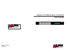
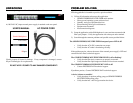
PRODUCT
DC POWER
CONNECTION
IDENTIFICATION
LABEL
FCC LABEL
EXTERNAL POWER SUPPLY
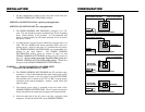
REAR VIEW
DB25
CONFIGURATION
SWITCHES
FIBER
OPTIC
LINK
Power
LED
Fiber
Status
LEDs
Polling
Group 1
Polling
Group 2